Product brochure
WaveSensor & WaveMaster® Brochure
Download
WaveSensor & WaveMaster®
Shack-Hartmann wavefront sensors
To ensure the implementation of the complex optical designs after production, a qualified measuring technology must be used. Wavefront measurement is particularly well-suited for this purpose, since it determines the image quality on a spatially-resolved basis, i.e. over all field angles, and across the entire sample aperture. In contrast to traditional MTF testing, this not only results in a point-based measure of quality, but also in a continuous alignment across the entire aperture.
Product Overview
These sensors analyze entire optical arrangements or individual surfaces in real time, delivering the determination of the wavefront (PV, RMS), the Zernike coefficients, the Point Spread Function (PSF), the Modulation Transfer Function (MTF), the Strehl ratio, the radius of curvature and the aspherical coefficients. They thereby enable conclusions to be drawn not only about quality control, but also about the production process.
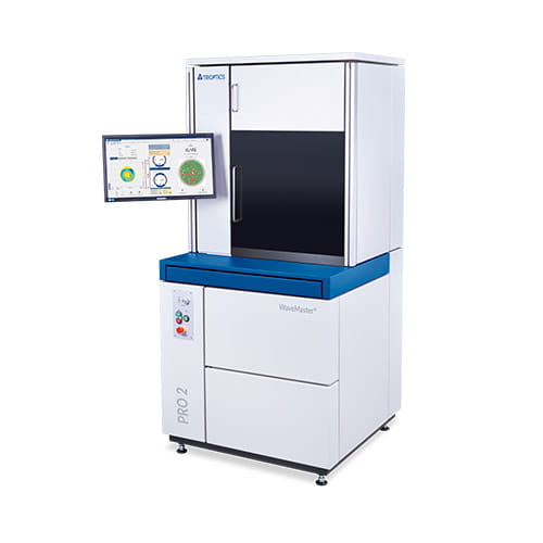
WaveMaster® PRO 2 / PRO 2 Wafer /
PRO 2 PLAN
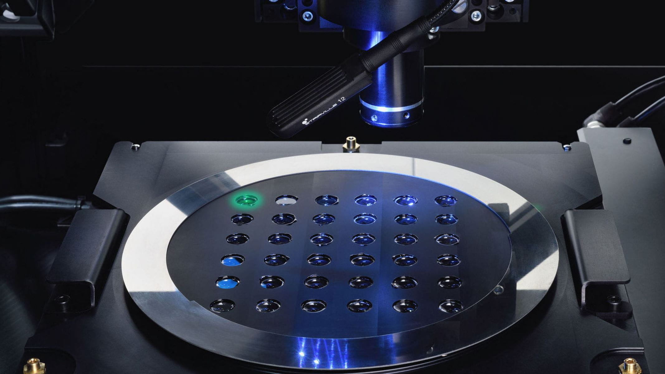
Serial testing of lens and wafers
WaveMaster® PRO 2 is used for series testing of lens assemblies and optical wafers
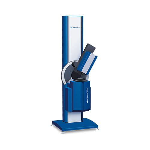
WaveMaster® Field
Off-axis wavefront measurement
The WaveMaster® Field is designed for testing single lenses and objectives under high field angles.
Applications
The demand for compact lens systems that are characterized by small size and low weight leads, in many cases, to the replacement of multiple spherical lenses with one aspherical optical arrangement. In addition, quality controls already performed during production are becoming more important. In many cases conventional processes cannot be used for these measurement tasks. Wavefront measurement with Shack-Hartmann sensors represents the solution of choice here, due to its large dynamic range.
Software
WaveSensor or WaveMaster® Software
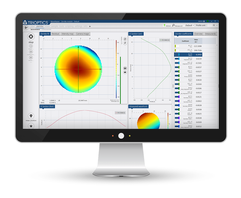
The software is comprehensively structured, user friendly and includes all of the functions required to measure and analyze spherical and aspherical samples with a WaveSensor®or WaveMaster®. As a result of their flexible configurability, all important measurement results are displayed.
The software communicates with the Shack-Hartmann sensor and analyzes the measured wavefront in real time. In addition, the WaveMaster® controls measurement systems in order to align samples, for example.
Technical Data
Shack-Hartmann Sensor
WaveSensor | 150 | 150 with reflex module |
---|---|---|
Sensor area | 15 mm x 15 mm | 15 mm x 15 mm |
Wavelength | 405 nm ... 1,100 nm1) | 405 nm ... 1,100 nm1) |
Wavefront accuracy | < λ/20 (RMS) | 0.05 μm (RMS) |
Wavefront repeatability | < λ/200 (RMS) | 0.005 μm (RMS) |
Dynamic range | 2,000 λ | 2,000 λ |
Measurement frequency | up to 12 Hz | up to 12 Hz |
Lateral resolution | 138 x 138 microlenses | 138 x 138 microlenses |
Research & Development
WaveMaster® | Compact 2 | Compact 2 Reflex | Compact 2 Universal |
---|---|---|---|
Sample diameter | 0.5 mm ... 14 mm2),3) | 4.5 mm ... 18 mm3),5) | Transmission: 0.5 mm ... 14 mm2),3) Reflection: 4.5 mm ... 14 mm3),5) |
Flange focal length | -30 mm ... +100 mm4) | -30 mm ... +100 mm4) | |
Radius of curvature | -50 mm ... 300 mm6) | -50 mm ... 30 mm6) | |
Sample holder | Single seat, manual positioning | Single seat, manual positioning | Single seat, manual positioning |
Maximum asphericity | ≤ 7°7) | ≤ 7°7) |
WaveMaster® | PLAN | Field | UST |
---|---|---|---|
Sample diameter | 0,5 mm ... 14 mm2), 3) | 0,5 mm ... 14 mm2), 3) | up to 1,100 mm x 650 mm x 1,200 mm |
Sample holder | Single seat, manual positioning | Single seat, manual positioning | Interface for customized lens holders |
Maximum sample weight | 450 kg | ||
Maximum distance between object and image plane | 1,200 mm | ||
Max. field dimensions image side | ±20 mm | 100 mm x 100 mm | |
Max. field dimensions object side | ±70° | 70 mm x 45 mm |
Production
WaveMaster® | PRO 2 | PRO 2 Wafer | PRO 2 PLAN |
---|---|---|---|
Sample diameter | 0.5 mm ... 14 mm2) | 0.5 mm ... 14 mm2) | 0.5 mm ... 14 mm2) |
FFL (Flange focal length) | -12 mm ... +50 mm2) | -12 mm ... +50 mm4) | |
Sample holder | Tray | Wafer holder | Tray |
Measurement time per lens | < 3 s8) | < 3 s8) | < 3 s8) |
Sample throughput per hour | ≥ 1,200 lens8) | ≥ 1,200 lens3) | ≥ 1,200 lens8) |
Lens per tray | Max. 1482) | Max. 1482) | |
Exchange time for tray of lenses | 10 s | 10 s | 10 s |
Wafer tray exchange time, incl. Alignment | < 2 min | < 2 min | < 2 min |
Setup time for new lens design | < 5 min | < 5 min | < 5 min |
1) In accordance with customer’s specification
2) Depending on telescope
3) More details upon request
4) Depending on microscope
5) Depending on radius of curvature and illumination lens
6) Depending on sample diameter and illumination lens
7) Local deviations from the best fit sphere
8) Depending on sample
Upgrades & Accessories
All of the WaveMaster® systems feature a flexible design and can thus be adapted to the specific requirements of your application.
A complete analysis is possible by an individual adjustment to the sample. Kinematic mounts enable the simple exchange of light sources and telescopes.
- Light sources with different wavelength and numerical aperture
- Telescopes for achieving optimal magnification between sample and sensor
- Lens assemblies for surfaces with different radii of curvature
- Sample holders and trays
- Reference samples
The software function is optimized by means of specific modules with regard to the measurement task:
ZERNIKE analysis module
- Zernike fit and analysis of the wavefront in real time
- Numerical and graphical display of fit results and residuals
- Import of wavefront design data from ZEMAX and CODE V for real-time comparisons
- Export of wavefront data and analysis results in ASCII and ZEMAX format
MTF/PSF analysis module
- Real-time calculation and display of 3D MTF and PSF data
- Table with MTF measurement results
- Export function for measurement results
- Calculation of Strehl ratio
- Extension of the measurement range
- Upgrade for toric lenses (automated marker detection, simplified measurement of MTF, visual inspection)
- Upgrade for 546 nm
- Lens holder with various aperture sizes
- Model eye, optional heatable
Knowledge Base
Wavefront measurement with Shack-Hartmann sensors
Operating principle of a Shack-Hartmann sensor and wavefront analysis
The standard design of a Shack-Hartmann sensor consists of a CCD camera which is placed in the focal plane of a microlens array. An incoming wavefront is sampled by the lenses of the microlens array and the foci form a spot pattern on the camera which would be evenly spaced in case of a plane wavefront. Any aberration introduced by the sample lens leads to a curvature of the wavefront thus resulting in local wavefront tilts. These induce a measurable shift of each focus spot position.
A numerical integration of the obtained slope information allows for reconstruction of the wavefront profile with high accuracy.
High dynamic range compared to interferometers
The dynamic range of a Shack-Hartmann sensor heavily depends on the algorithm which assigns each measured spot to the corresponding microlens. A wavefront is reconstructed only when this correlation is kept. Especially in case of stronger curved wavefronts sophisticated algorithms are needed since the simple assignment of a predefined searching area in the CCD plane of the size of a microlens is not sufficient anymore. Modern techniques achieve wavefront dynamic ranges up to 1500 A.
Due to this high dynamic range Shack-Hartmann sensors are able to measure wavefronts with strong aberrations which are not accessible with interferometers anymore.
More knowledge for experts
This article inspired you? Are you looking for further knowledge transfer?
Then you might also be interested in the following topics …
Real time wavefront analysis zernike polynomials
The measured wavefront is decomposed into a linear combination of Zernike polynomials which describe typical optical properties and errors of a lens or lens system as e.g. defocus, coma or astigmatism.
The polynomial decomposition gives a numerical representation of any kind of aberration of the sample. These have basically two sources: aberrations directly linked to the design of the lens, most likely spherical terms, and asymmetric contributions due to lens errors.
MTF, PSF and Strehl ratio
The effects of aberrations are also characterized by calculating the Point Spread Function (PSF), Modulation Transfer Function (MTF or Strehl ratio of the optical system which are obtained from the wavefront. The MTF is as well-known as the modulus of the Optical Transfer Function.
The wavefront measurement and its further analysis give a full spatially resolved description of the imaging characteristics of the lens under test.
Different setups with Shack-Hartmann sensors
Measurement setups in transmission and reflection
Different configurations of the setup can be chosen for measuring the wavefront. Most important for the choice of configuration is whether the optical properties – using the transmission mode – or the lens shape – using the reflection mode – shall be analyzed
Transmission mode
Measurement in transmission provides information about the optical properties of the lenses or lens systems combining the influence of all surfaces as well as refractive index variations in the measured wavefront.
Basic infinite setup
In the basic transmission setup the sample lens is illuminated with collimated light. A lens in combination with a telescope is then used to collimate the beam again and image the wavefront onto the Shack-Hartmann sensor.
In this setup the sample lens can be easily adjusted in its lateral and height position to achieve the best focus position with respect to the sensor.
Reverse infinite setup
In this configuration the sample lens is illuminated by a point light source in the focal plane of the lens. The exit pupil of the lens is imaged onto the wavefront sensor by a telescope.
The height position of the point light source, the lateral position of the sample lens and the image plane of the Shack- Hartmann sensor are chosen separately. The reverse infinite setup is used for the instruments WaveMaster® Compact 2 and WaveMaster® PRO.
Finite setup
In addition to the reverse setup, the lens is illuminated and tested in a configuration which is equal or close to the conditions of its dedicated application. This means the point light source is not located in the focal plane of the specimen, but at a distance specified by the design. For the complete imaging of the beam on the sensor, a collimating lens is added between sample lens and telescope. In this configuration. This configuration is only available with the instrument recommended for research and development.
Reflection mode
Measurements in reflection provide information about the topography of the sample surface. For this measurement the illumination unit with beam splitter is mounted in front of the wavefront sensor. A combination of collimating lens and telescope is used to illuminate the sample and image the reflected wavefront onto the Shack-Hartmann sensor.
The reflection setup is available as an easy to attach module for all WaveSensor products. Single lesnes can be measured with using WaveMaster® Compact 2 Reflex and WaveMaster® Compact 2 Universal.