Wavefront & interferometry measurement
The demands on the quality of optics are constantly increasing. The applications for the development of lens designs are also increasing and the theoretical calculations of the image – on-axis and off-axis - are becoming more demanding. Qualified measurement technology must also be used to ensure the implementation of complex optical designs after production. Wavefront testing or interferometry, which determines the image quality with spatial resolution, i.e. across all field angles and across the entire test sample aperture, is particularly suitable for this purpose. In contrast to classic MTF testing, this results not only in a selective measure of quality, but a continuous adjustment for the entire aperture.

WaveMaster® – Complete systems for wavefront testing based on a Shack-Hartmann sensor for steep wavefronts.
Shack-Hartmann sensors analyze entire optical arrangements or individual surfaces in real time, delivering the determination of the wavefront (PV, RMS), the Zernike coefficients, the Point Spread Function (PSF), the Modulation Transfer Function (MTF), the Strehl ratio, the radius of curvature and the aspherical coefficients. They thereby enable conclusions to be drawn not only about quality control, but also about the production process.
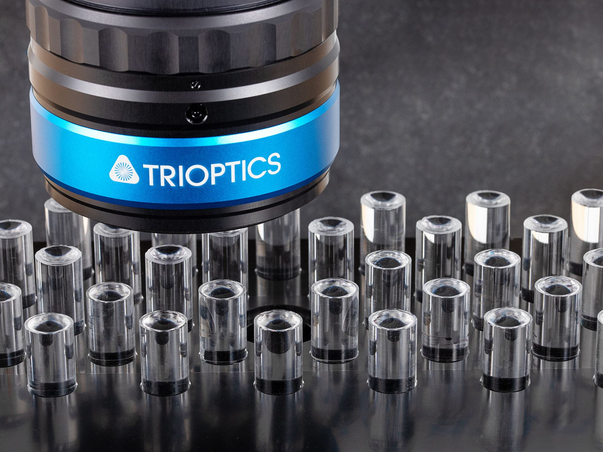
µPhase®– Surface and wavefront measurements using interferometers with high accuracy requirements.
µPhase® interferometers permit fast, high-precision measurements of the surface and wavefront deformation of reflective and transmitting components made from glass, plastics, metal, ceramics or similar materials. The objective and reliable results fulfill the highest quality management requirements. The non-contact measurement process helps prevent damage to the sample.

OptoFlat® – Short coherence interferometer specialized in the measurement of flat optics.
OptoFlat is a production ready and research capable flatness interferometer with sub-nanometer precision.
Knowledge base
Operating principle of a Shack-Hartmann sensor and wavefront analysis
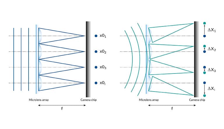
The standard design of a Shack-Hartmann sensor consists of a CCD camera which is placed in the focal plane of a microlens array. An incoming wavefront is sampled by the lenses of the microlens array and the foci form a spot pattern on the camera which would be evenly spaced in case of a plane wavefront. Any aberration introduced by the sample lens leads to a curvature of the wavefront thus resulting in local wavefront tilts. These induce a measurable shift of each focus spot position. A numerical integration of the obtained slope information allows for reconstruction of the wavefront profile with high accuracy.
High dynamic range compared to interferometers
The dynamic range of a Shack-Hartmann sensor heavily depends on the algorithm which assigns each measured spot to the corresponding microlens. A wavefront is reconstructed only when this correlation is kept. Especially in case of stronger curved wavefronts sophisticated algorithms are needed since the simple assignment of a predefined searching area in the CCD plane of the size of a microlens is not sufficient anymore. Modern techniques achieve wavefront dynamic ranges up to 1500 A. Due to this high dynamic range Shack-Hartmann sensors are able to measure wavefronts with strong aberrations which are not accessible with interferometers anymore.Real time wavefront analysis zernike polynomials
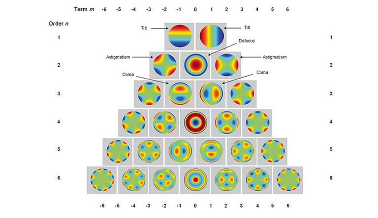
The measured wavefront is decomposed into a linear combination of Zernike polynomials which describe typical optical properties and errors of a lens or lens system as e.g. defocus, coma or astigmatism. The polynomial decomposition gives a numerical representation of any kind of aberration of the sample. These have basically two sources: aberrations directly linked to the design of the lens, most likely spherical terms, and asymmetric contributions due to lens errors.
MTF, PSF and Strehl ratio
The effects of aberrations are also characterized by calculating the Point Spread Function (PSF), Modulation Transfer Function (MTF or Strehl ratio of the optical system which are obtained from the wavefront. The MTF is as well-known as the modulus of the Optical Transfer Function.
The wavefront measurement and its further analysis give a full spatially resolved description of the imaging characteristics of the lens under test.
Different setups with Shack-Hartmann sensors
Measurement setups in transmission and reflection Different configurations of the setup can be chosen for measuring the wavefront. Most important for the choice of configuration is whether the optical properties – using the transmission mode – or the lens shape – using the reflection mode – shall be analyzed
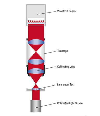
Transmission mode
Measurement in transmission provides information about the optical properties of the lenses or lens systems combining the influence of all surfaces as well as refractive index variations in the measured wavefront.
Reverse infinite setup
In this configuration the sample lens is illuminated by a point light source in the focal plane of the lens. The exit pupil of the lens is imaged onto the wavefront sensor by a telescope. The height position of the point light source, the lateral position of the sample lens and the image plane of the Shack- Hartmann sensor are chosen separately. The reverse infinite setup is used for the instruments WaveMaster® Compact 2 and WaveMaster® PRO.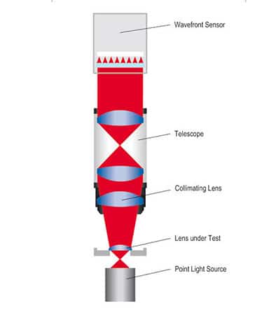
Finite setup
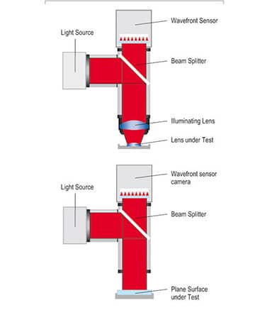
In addition to the reverse setup, the lens is illuminated and tested in a configuration which is equal or close to the conditions of its dedicated application. This means the point light source is not located in the focal plane of the specimen, but at a distance specified by the design. For the complete imaging of the beam on the sensor, a collimating lens is added between sample lens and telescope. In this configuration. This configuration is only available with the instrument recommended for research and development.
Reflection mode
Measurements in reflection provide information about the topography of the sample surface. For this measurement the illumination unit with beam splitter is mounted in front of the wavefront sensor. A combination of collimating lens and telescope is used to illuminate the sample and image the reflected wavefront onto the Shack-Hartmann sensor.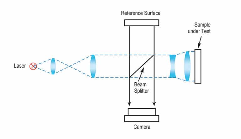
Twyman-Green setup
Twyman-Green setup
The most flexible interferometer setup
A Twyman-Green interferometer is a modified Michelson interferometer. Here the beam splitter is separated from the reference surface. The advantage of this configuration is greater flexibility, because both interferometer arms can be modified independently of each other. So the intensity of the reference and test arm can be easily adapted to each other depending on different sample reflectivities in order to get maximum fringe contrast. This increases the range of applications enormously. Only a maximum fringe contrast enables a maximum resolution in depth. The reference surface can be a surface that is inexpensive and accurately producible regardless of the sample size. The adaption to the sample size is done by conventional beam shaping optics introduced to the test arm. Contrary to the beam shaping optics for Fizeau interferometers these optics do not require an expensive Fizeau surface as a final surface.
As a consequence of this flexibility, the interference patterns are not caused by the sample errors only but also by the aberrations of the additional optics in the individual interferometer arms. However, nowadays samples are no longer evaluated by visual inspection of the fringe pattern but by computer controlled analysis of the phase map causing the fringe pattern. During this analysis the aberrations of the additional optics can easily be taken into account. Finally, the software provides an objective digital measurement result.
Fizeau construction
Fizeau interferometer for wavefront and surface measurement
Fizeau setup
The most commonly used interferometer setup
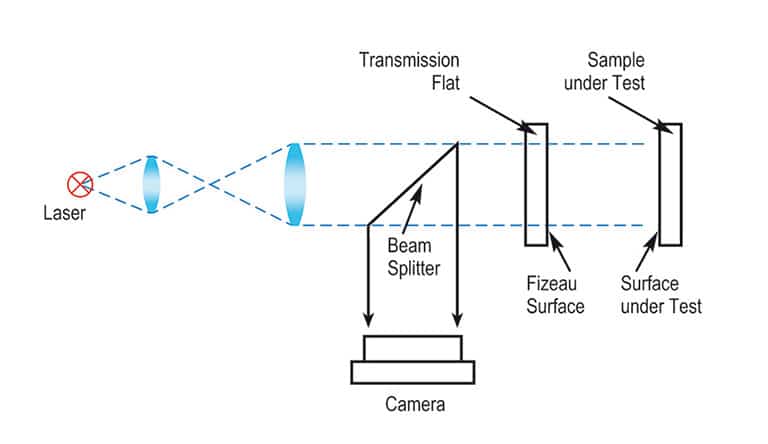
The last surface of the beam shaping optics is the so called Fizeau surface. It has to have the same shape as the sample to be tested (commonly spherical or flat) and is placed concentrically into the optical path, so the individual rays intersect perpendicular to the Fizeau surface. The majority of the light passes the Fizeau surface and is reflected at the test surface. The returning light interferes with the part of the light reflected at the Fizeau surface. So the Fizeau surface acts as beam splitter as well as reference surface. So the cavity is formed by the gap between the Fizeau and the test surface containing no additional optics. That is the reason why a Fizeau interferogram commonly directly shows the deviations of the test sample from the reference surface, i.e. Fizeau surface. The quality of the Fizeau surface determines the accuracy of the Fizeau interferometer. Fizeau surfaces are commonly available with a quality of λ/10 – λ/20 PV, better on request.
Our Newsletter – Your advantage in knowledge
Be one of the first to experience our product novelties and innovative application possibilities.
