Measurements with autocollimators
Autocollimators are a combination of collimator and telescope sharing the same optical path via a beam splitter. Via the collimator functionality, the structure engraved on the reticle is imaged to infinity. The device under test is placed in the optical path and reflects the light back into the autocollimator. This reflected light is imaged into the camera plane of the autocollimator via the telescope funcitonality.
A typical application is the measurement of the tilt angle of the surface that reflects the light back into the autocollimator.
Angle measurement of optical components
Wedge- and deflection angle
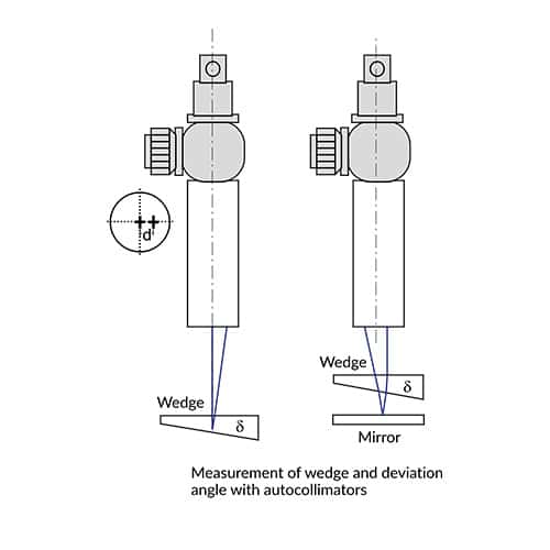
The parallel beam emerging from the autocollimator is reflected from both surfaces of the wedge. The wedge angle δ is given by:
δ = d/(2nf)
where:
d = displacement of the reflected image n-refractive index of glass
f = focal length of the autocollimator
For fast measurement in optical manufacturing, the displacement d for a given angle tolerance and focal length f can be calculated and transferred to the illuminated reticle in form of a pinhole, so that the ascertainment of the component can be made on a „go“ and „no go“ basis:
A) Wedge out of tolerance
B) Wedge at the tolerance limit
C) Wedge in tolerance
The deflection angle through the wedge is given for small angles by:
γ = d(n-1)/(2nf)
Internal angle of 90° prisms
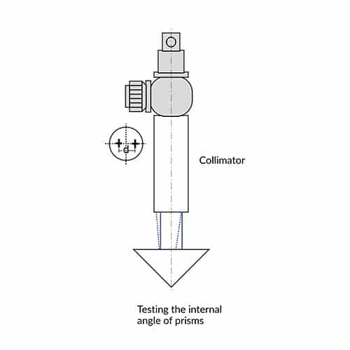
The reflected images from the 90° sides (which are insensitive against rotation around the roof edge) are diplaced by an amount x, if a deviation from 90° angle α is present.
A presence of a displacement in height by the amount y proves a pyramid error ϓ:
α = X/(4nf)
γ = Y/(4nf)
n = refractive index of glass
f = focal length of the autocollimator
90° angle of prisms
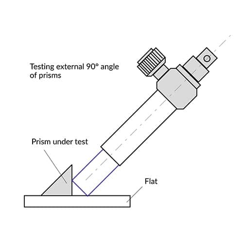
α = d / (4f)
where f= focal length of autocollimator. The sign -/+ of the error is determined by defocusing the eyepiece: Moving the focal plane of the eyepiece towards objective lens, a negative error results if the distance d becomes smaller.
45° angle of prisms
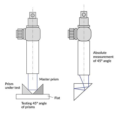
Measuring the 45° angle of a prism two methods are possible:
a) Relative measurement of 45°-angle
To measure the 45° angle a master prism is used. Both prisms are put on an accurate flat. The 90° angle of the prism under test must be checked first, since the error of this angle will influence the measurement.
b) Absolute measurement of 45°-angle
The autocollimator is directed on one side of the 90° angle. Two images will be produced from both sides of the prism. The internal reflection within the prism will produce a displacement d depending on the error of the 45° angle α:
α = d/(4nf) ± δ/2
where δ is the error of 90° angle.
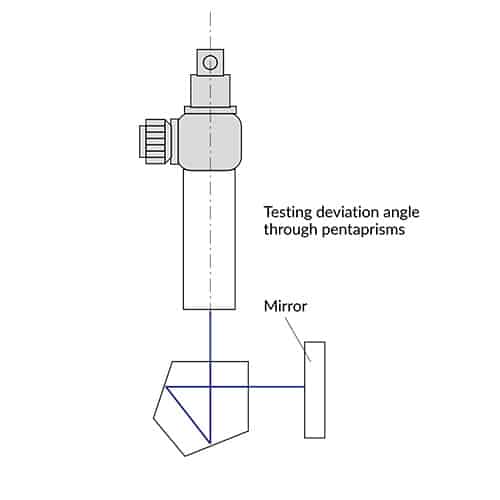
Deviation angle through prisms
Checking the straightness, squareness, parallelism and flatness
The measurement of geometrical parameters of mechanical parts is a typical application in machine construction, machine tools and aerospace industry.Straightness

A mirror is either moved along the surface or mounted on a movable part of the machine to be measured. The mirror is supported by balls or pins placed at a distance b known as base length. Deviations from straightness will result in tilt of the mirror. Deviation from straightness are given by:
h = b tan α
where:
α = mirror tilt
b = base length
When computerized or electronic autocollimators are used, readings can be automatically entered into computer. The software program permits straightness measurement on machine tool slideways, shafting, stages, rolls etc.
Flatness
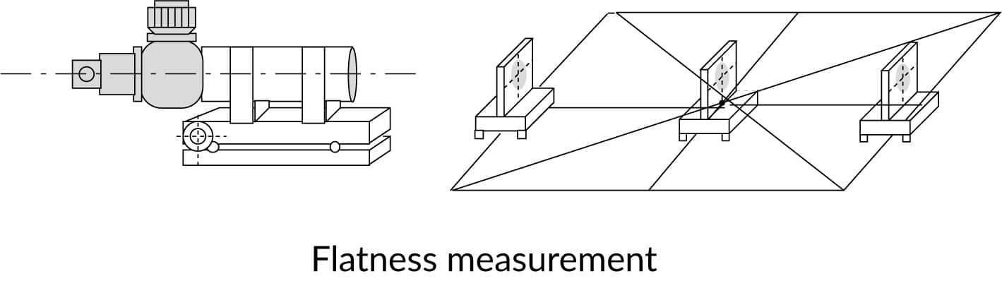
The base mirror is moved along diagonals and rectangles of the surface to be measured. Along each line a straightness measurement is carried out. The data from surface generators lines are used to calculate the shape of the surface and the deviations from flatness.
The data can be entered into a computer to produce a topography of the surface under test.
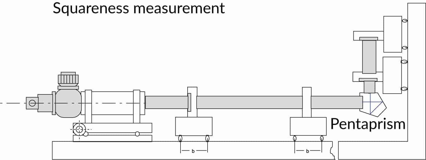
Squareness
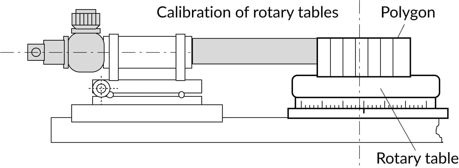
Rotary tables
Parallelisms of bearings
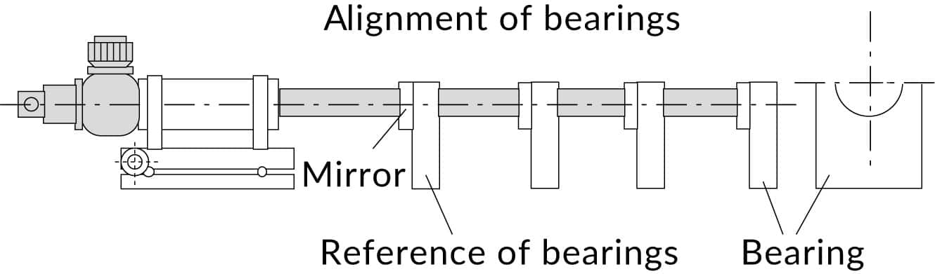
The reference surface is aligned to the autocollimator. The autocollimator is fixed in this position. The mirror is transferred to next surface which is aligned to the same autocollimator.
After the first bearing is squared to autocollimator, the mirror is transferred to the next bearing. Deviation from parallelism is read and the bearing aligned.
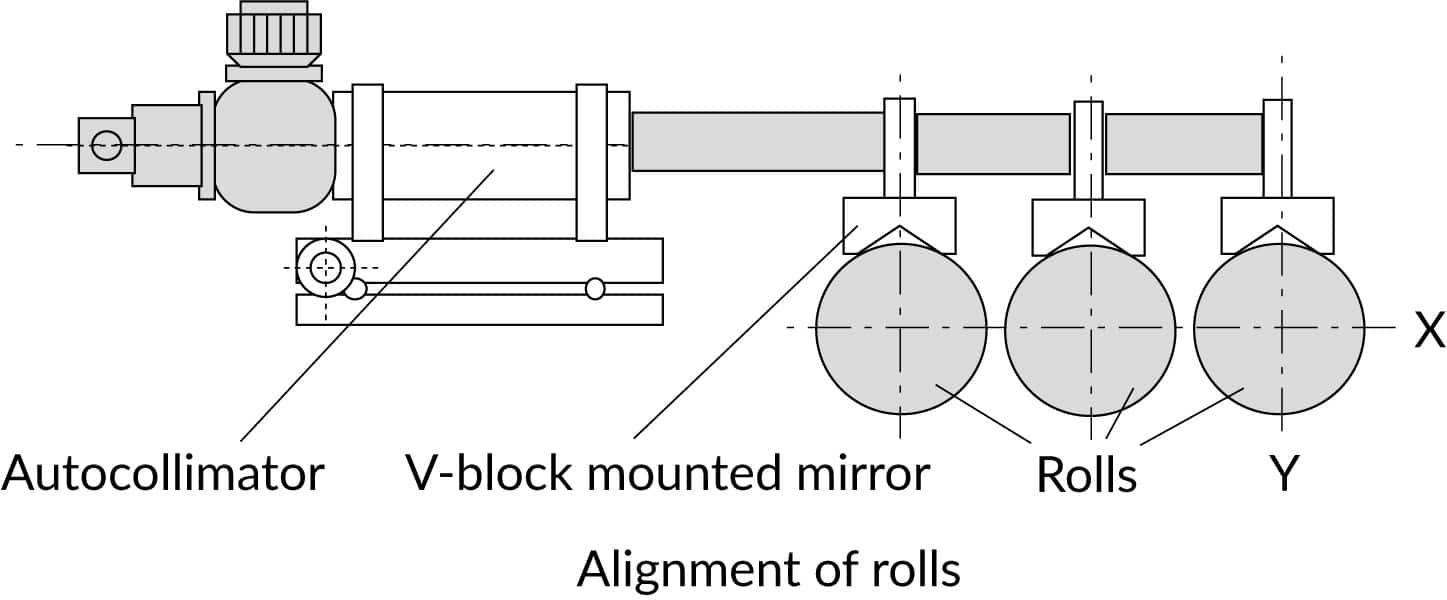
Parallelisms of rolls
Measurement of oprical ad optomechanical parameters
Radius of curvature
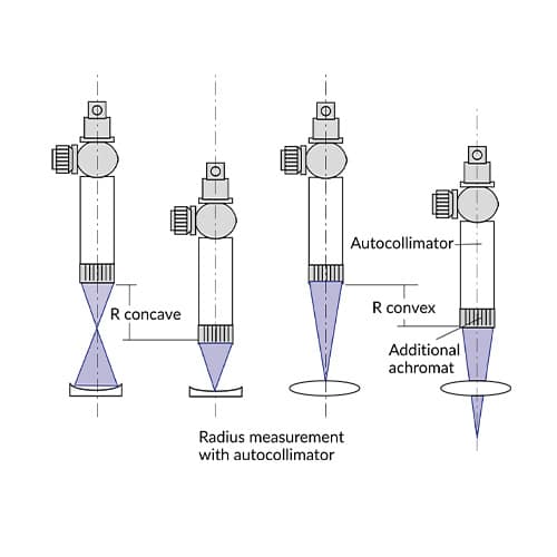
Additional achromats are mounted on the one end of the autocollimator tube. The illuminated image of the autocollimator will be projected into the focal plane of the achromat. This image is reflected back from the vertex of the sample and the center of curvature of sample’s surface. The linear displacement between these two positions – where a sharp image is seen in the eyepiece – gives the radius of curvature.
Both concave and convex surfaces can be measured. Spherical and cylindrical surfaces can be measured as well. For convex surfaces the back focal length of the achromat must be longer than the radius under test.
Radius of curvature – flat surfaces
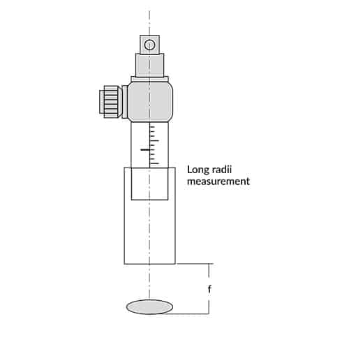
For measurement of very long radii of curvature focusing autocollimators with draw out tubes can be used. Drawing out the tube with the autocollimation head, the autocollimator can be focused on the lens vertex and center of curvature. Since the nearest focus point for a focusing autocollimator is in a distance of some meters and the focusing on the vertex is practically difficult, following configuration is recommended:
The lens under test is positioned with the vertex at a distance f from autocollimator lens (f = effective focal length EFL of the autocollimator). After focusing in the center of curvature of the lens, the radius is given by:
R = f²/d
where d = displacement of the draw out tube read off on its scale.
Flange focus
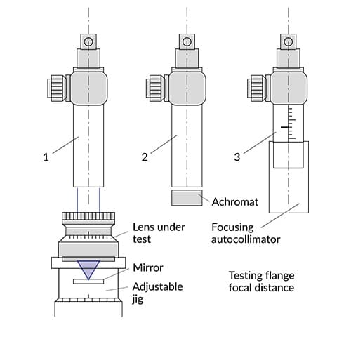
The flange focus known also as Flange Focal Length (FFL) or Flange Focal Distance (FFD) is the distance between the locating surface of the lens mount and the image plane. Checking and setting of this distance is important especially for camera lenses. The film plane is replaced by a mirror mounted on an adjustable jig.
For checking the FFL when the lens under test is set to infinity a standard autocollimator (1) is used. For testing the lens set at other distances as infinity is recommended:
- achromats attached to the autocollimator for short distances (2)
- a focusing autocollimator for infinity and long distances (3)
The reticle normally used is a Siemens Star. When the reticle is sharply seen at the given distance, the camera lens is correctly set. Deviations can be measured with an adjustable jig and the lens correspondingly adjusted.
Centration errors
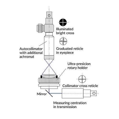
The autocollimators can be used for measurement of centration errors in transmission (see collimators applications) or in reflection:
For measurement in reflection additional achromats are attached to autocollimator. The precision rotary holder is equipped with a chuck running true to the rotation axis. The spherical surface under test is located on the front surface of the chuck and held in contact by means of a small vacuum device. When rotated, the surface under test will reflect the image reticle. This image describes a circle with a diameter depending on the decentration size.
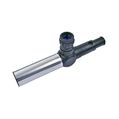
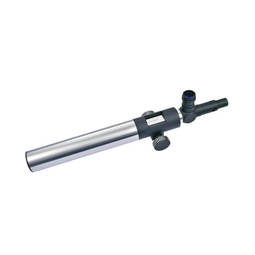
Our products
Our autocollimators are part of the OptiTest® product group. They are available in the following variants:

Knowledge Base
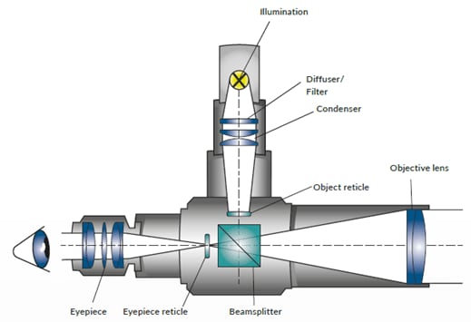
Autocollimation is an optical technique of projecting an illuminated reticle to infinity and receiving the reticle image after reflection on a flat mirror. The reflected image is brought to the focus of the objective lens in which the eyepiece reticle is located. Thus the reflected image of the collimator (illuminated) reticle and the eyepiece reticle can be simultaneously observed. When the collimated beam falls on a mirror which is perpendicular to beam axis, the light is reflected along the same path. Between the reflected image and the eyepiece reticle -which are seen superimposed – no displacement occurs.
If the reflector is tilted by an angle α, the reflected beam is deflected by twice that angle i.e. 2α. The reflected image is now laterally displaced with respect to the eyepiece reticle. The amount of this displacement „d“ is a function of the focal length of the autocollimator and the tilt angle of the reflector: d=2 α f. (α in radians).The tilt angle can be ascertained with the formula:
α = d/(2f)
where f is the effective focal length EFL of the autocollimator. Since the f is a constant of the autocollimator, the eyepiece reticle can be graduated in angle units and the tilt angle can be directly read off.
