Measurements with collimator and industrial telescope
Angle measurement
Angle measurement
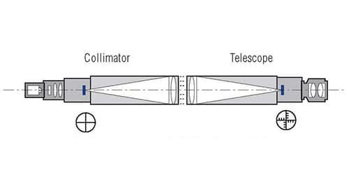
A telescope mounted in the front of a collimator enables the simultaneous observation of both collimator and telescope reticle. When a collimator is perfectly aligned to a telescope the reticles are superimposed and no displacement occurs.
The presence of an angle α between the collimator and telescope axes is shown by a linear displacement d between the two reticles. The displacement d gives the size of the angular disalignment (in radians) of the two instruments:
α = d/f
where:
d=linear displacement measured in the reticle plane (focal plane)
f=effective focal length (EFL) of the observing instrument (i.e. telescope)
To ease the angular alignment of equipment with flat surfaces a special type of instruments can be used: the square body collimators and telescopes. The reticles of these instruments are accurately aligned to the outer square body surfaces.
Since collimators and telescopes used for angle measurement have a standard infinity setting and therefore the beams of the instruments are parallel, the measurement is not affected:
- when a parallel displacement of the optical axes occurs
- when the distance between the instrument is modified
Measurement of the transmission angle through prisms
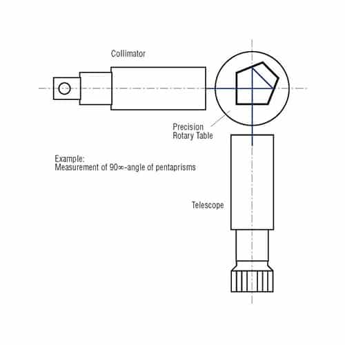
Absolute measurement: The telescope is attached to a precision rotary table with read out:
First reading: collimator and telescope aligned (without sample)
Second reading: sample positioned, telescope rotated until the reticles are super imposed. Reading on rotary table.
Relative measurement: a master prism is used, collimator and telescope rotated until reticles are super imposed and fixed in this position. The sample is placed instead of master prism. Reading on telescope.
- TRIOPTICS Autocollimators
- Eyepiece reticles: angle graduated scales
- Collimator reticles: single cross line: RET-02 (RET-01, RET-12, RET-04)
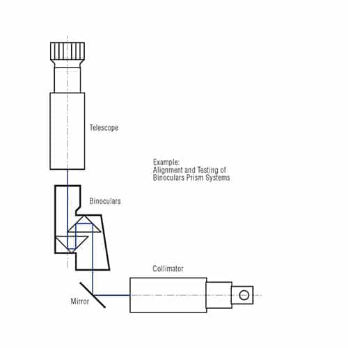
Alignment of prism systems
Option 1:
- Option TRIOPTICS OptiAngle
- Eyepiece reticles: double cross line
- Collimator reticles: single cross line
Preferred combinations:
- RET-24/RET-02
- RET-24/RET-12
- RET-24/RET-13
- RET-02/RET-12
- RET-22/RET-01(f <300 mm)
Option 2:
- TRIOPTICS OptiAngle
- Eyepiece reticle: mm scales
- Collimator reticle: Porro plates, slits patterns, etc.
Preferred combinations
- RET-71/RET-13(RET-02)
- RET-91/RET-13 (RET-02, RET-86)
- RET-02/RET-73
Measurement of optical parameters
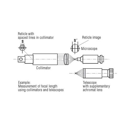
Measurement of focal length
- TRIOPTICS OptiAngle
- Eyepiece reticle: mm scales
- Collimator reticle: Porro plates, slits patterns, etc.
Preferred combinations:
- RET-71/RET-13(RET-02)
- RET-91/RET-13 (RET-02, RET-86)
- RET-02/RET-73
Measurement of centration errors
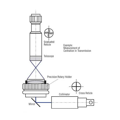
A collimator set to infinity contains a reticle with a dark or bright cross. The lens under test is placed in a precision rotary holder. The image of a reticle projected over the lens under test is observed by means of a telescope with additional achromat having a graduated reticle.
While rotating the holder with the lens, the circle described by the reticle image is measured.
Option 1:
- Option TRIOPTICS OptiAngle
- Eyepiece reticles: double cross line
- Collimator reticles: single cross line
Preferred combinations:
- RET-24/RET-02
- RET-24/RET-12
- RET-24/RET-13
- RET-02/RET-12
- RET-22/RET-01(f <300 mm)
Option 2:
- TRIOPTICS OptiAngle
- Eyepiece reticle: mm scales
- Collimator reticle: Porro plates, slits patterns, etc.
Preferred combinations:
- RET-71/RET-13(RET-02)
- RET-91/RET-13 (RET-02, RET-86)
- RET-02/RET-73
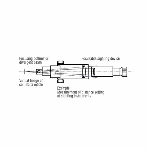
Measurement of the focusing distances
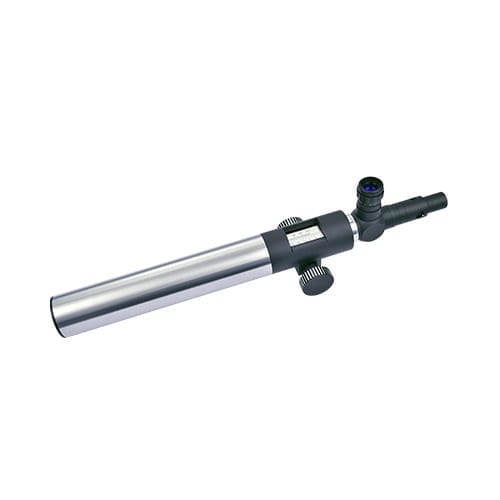
Our products
Our telescopes and collimators are combined in the OptiTest® product group. They are available in the following variants:


Knowledge Base
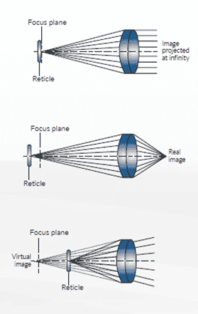
Illustration 1
The reticle is placed at the lens focal plane. The emerging beam is collimated, meaning that all rays originated from the same point on the reticle plane are parallel to each other. The image of the reticle is said to be projected to infinity because parallel rays will not cross at a finite distance.
Illustration 2
The reticle is placed beyond the focal plane
of the objective lens. The emerging beam is convergent, meaning that rays originated from the same point on the reticle plane meet again at a single point on the right side of the lens, leading to the formation of a real image at a finite distance.
Illustration 3
The reticle is placed between the lens and its focal plane. The emerging beam is divergent and there exists an apparent crossing point on the left side of the lens which is equivalent to an object placed at that point from where the divergent rays are originated. This image is said to be virtual.
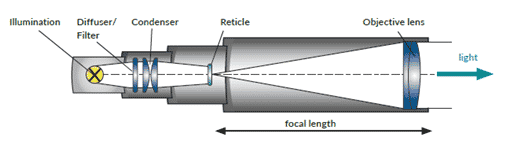
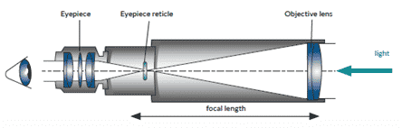
Fig. 3 Schematic cross section of a telescope. Visual inspection by an eyepiece.