OptiCentric®
High-precision centration test devices, alignment, cementing and bonding systems
Precise
Flexible
Sophisticated
Products
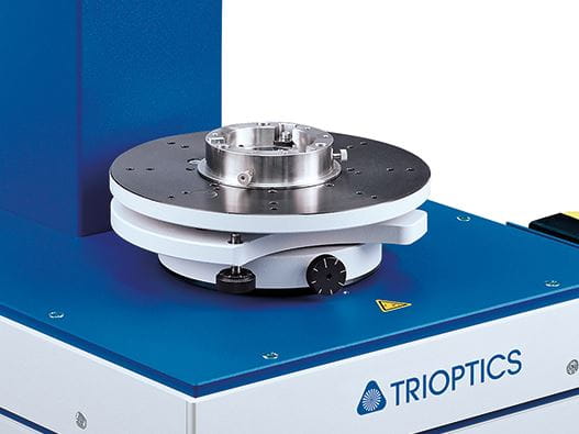
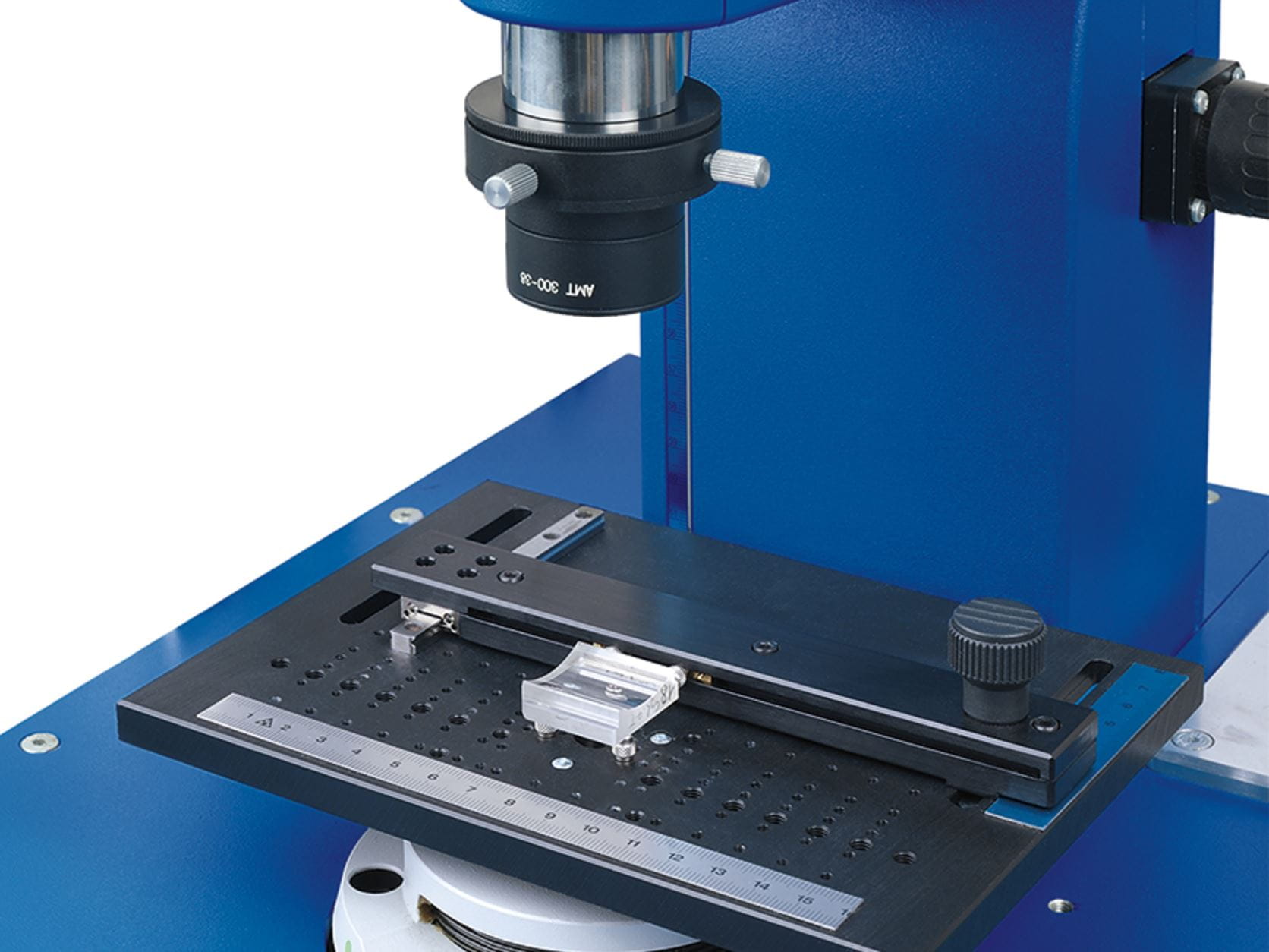
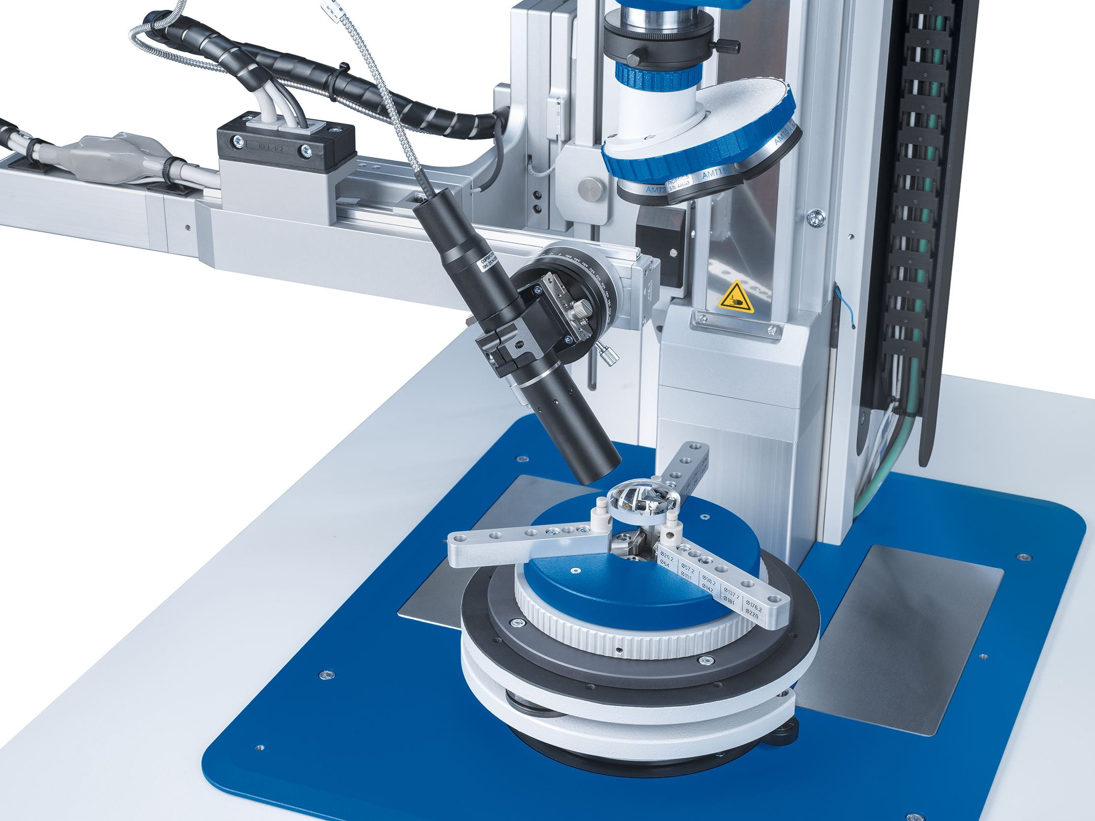
To make measurement of these different sample dimensions possible, the measurement head is mounted to a height-adjustable stage. The measurement point of the autocollimator measurement head can be moved flexible and precisely into the measurement position of the sample by a motorized fence. The entire measurement process, for example for measurement and alignment of multilens assemblies, can be fully automated.
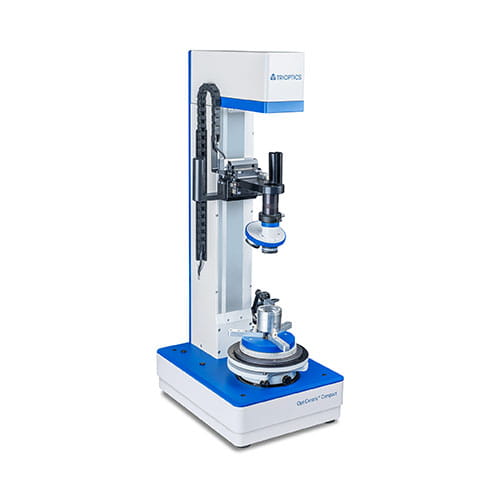
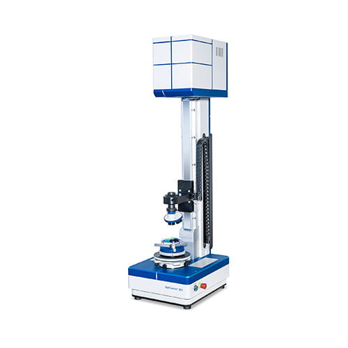
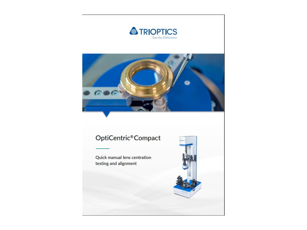
OptiCentric® Compact
Manual centration testing and lens alignment
OptiCentric® Compact allows quick and easy measurement and alignment of single lenses in a manual, user-friendly inspection process.
- Manual focusing with little set-up times
- Optional lens rotation unit: Manually driven rotating air bearing or lens rotation device
- Precision < 0.1 µm
- Software optimized for the manual process
- Manually driven rotary air bearing or lens rotation device
- Compact design with all-in-one PC
The OptiCentric® Compact is available in two configurations:
- OptiCentric® Compact is most ideal for measuring the centration of single lenses with respect to the lens edge using a motorized lens rotation device or for measuring cylindrical lenses using the CylinderCheck® module.
- OptiCentric® Compact AB is recommended for manual lens bonding and cementing using a manually driven rotary air bearing.
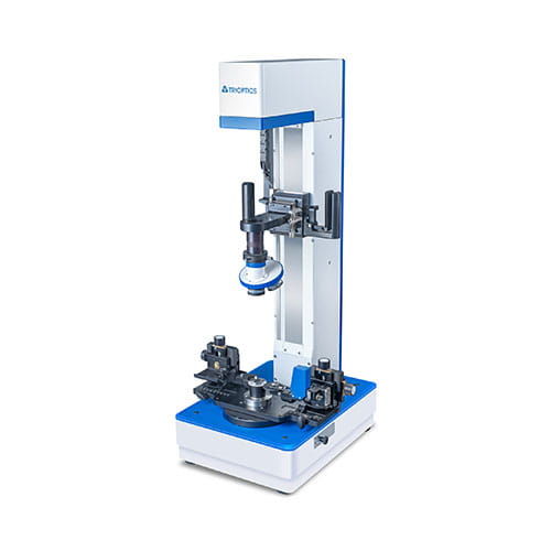
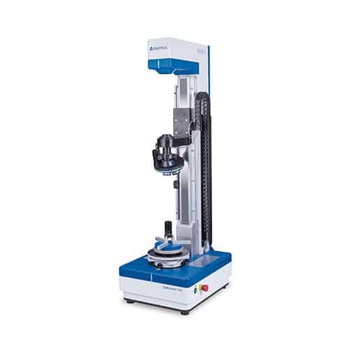
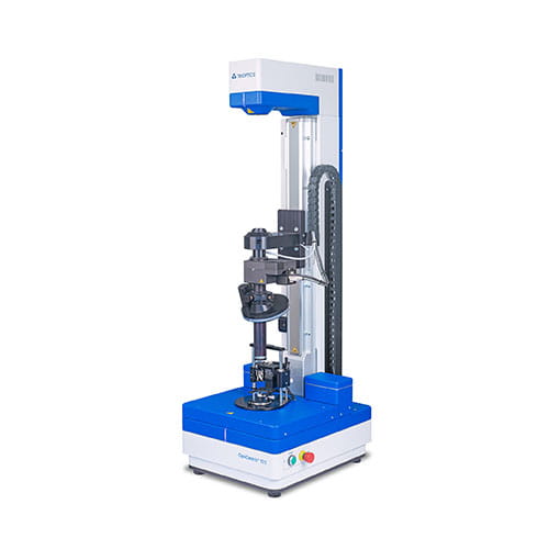
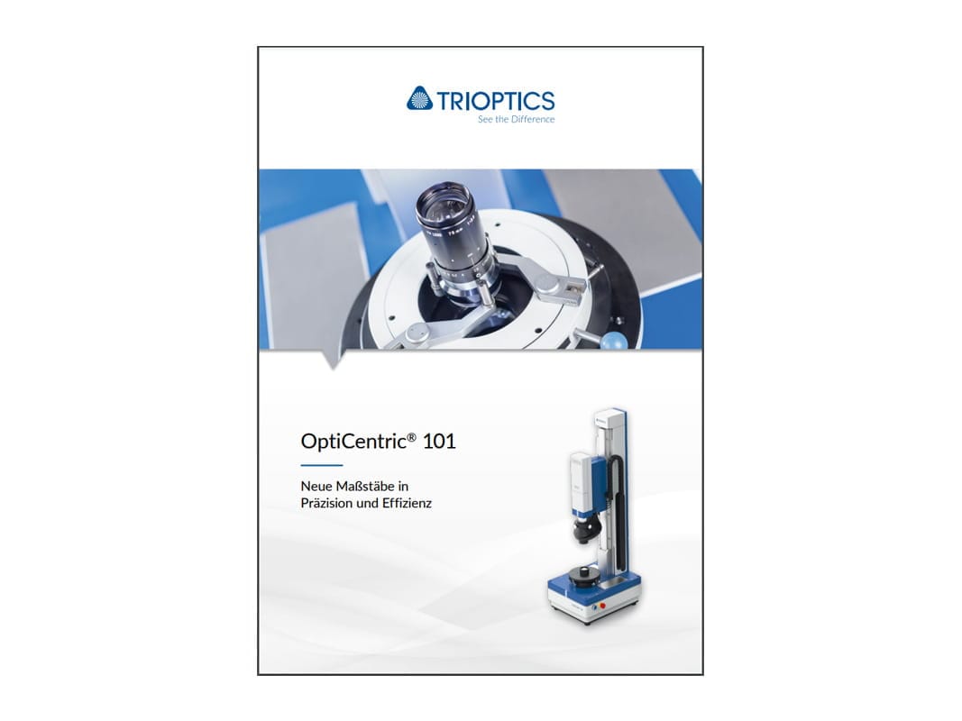
OptiCentric® 101
Centration testing taken to a new level
With its especially stable structure and an increase in processing speed by the factor of 4, the OptiCentric® 101 is increasing precision and efficiency.
- Lens diameter from 0.5 mm to 225 mm
- Precision < 0.1 µm
- Maximum sample weight of 20 kg on adjustment table
- Motorized or manual stage with 500 mm travel path as standard
The OptiCentric® 101 is available in two layouts:
- Static autocollimator:
With this setup, the autocollimator is positioned statically above the travel axis. This reduces the influences of the stage rolling faults and contributes to improved recording of the azimuth angle e.g. during cylinder lens measurements. The autocollimator can also perform a linear centering error measurement.
- Moving autocollimator:
This traditional setup, where the autocollimator moves on the axis, minimizes the influences of vignetting.
The OptiCentric® 101 can be configured in a modular way depending on individual requirements.
You will find further information on the expansion stages further down on this page.
Upgrades for further measurement tasks:
- Measurement system without air bearing with static autocollimator
OptiCentric® 101 basic
- Measurement system without air bearing with moving autocollimator
OptiCentric® 101 basic M
- Measurement system with air bearing and static autocollimator
OptiCentric®
- Measurement system with air bearing and moving autocollimator
OptiCentric® 101 M
- Testing of lens systems with more than 20 surfaces with static autocollimator
OptiCentric® 101 Dual
- Testing of lens systems with more than 20 surfaces with moving autocollimator
OptiCentric® 101 Dual M
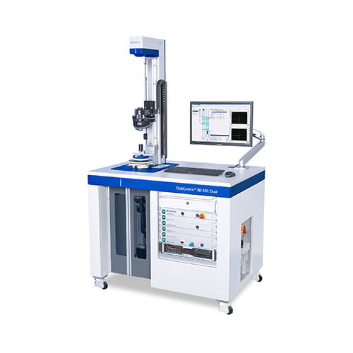
- Centration testing in combination with center thickness and air gap measurement with static autocollimator
OptiCentric® 3D 101
- Centration testing in combination with center thickness and air gap measurement with moving autocollimator
OptiCentric® 3D 101 M
- Centration testing of lens systems with more than 20 surfaces in combination with center thickness and air gap measurement with static autocollimator
OptiCentric® 3D 101 Dual
- Centration testing of lens systems with more than 20 surfaces in combination with center thickness and air gap measurement with moving autocollimator
OptiCentric® 3D 101 Dual M
- Centration testing in combination with the testing of effective focal length and back focal length, flange focal length, radius and MTF
OptiCentric® 101 with OptiSpheric®
- Centration test for cylinder lenses
OptiCentric® 101 with CylinderCheck®
- Centration testing of aspheres
OptiCentric® 101 with AspheroCheck®
Upgrades for production tasks:
- Manual alignment on the lens rotation device
lens rotation device
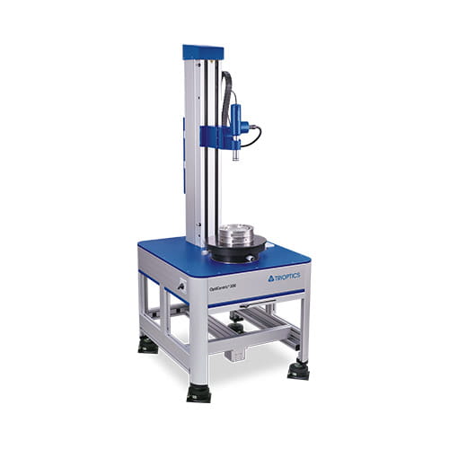
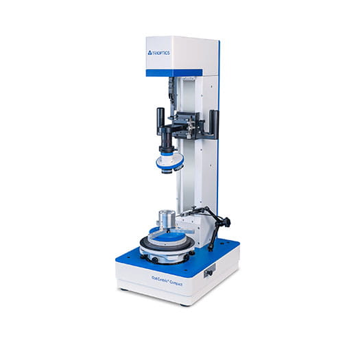
OptiCentric® 300
Reliable determination of the centration of large samples
The OptiCentric® 300 can be used for measuring and aligning lenses with a diameter of up to 400 mm.
- Precision < 0.1 µm
- Maximum axial sample weight of 100 kg (without adjustment table)
- Motorized stage with a travel path of 990 mm
The OptiCentric® 300 can be configured in a modular way depending on individual requirements
You will find further information on the expansion stages further down on this page.
Upgrades for further measurement tasks:
- Testing of lens systems with more than 20 surfaces
OptiCentric® 300 Dual
- Centration testing in combination with center thickness and air gap measurement
OptiCentric® 3D 300
- Centration testing of lens systems with more than 20 surfaces in combination with center thickness and air gap measurement
OptiCentric® 3D 300 Dual
- Testing of VIS and IR lens systems
OptiCentric® 300 IR
- Centration testing of VIS and IR lens systems in combination with center thickness and air gap measurement
OptiCentric® 3D 300 IR
- Centration testing of VIS and IR lens systems in combination with center thickness and air gap measurement
OptiCentric® 300 Dual IR
- Centration testing of VIS and IR lens systems with more than 20 surfaces in combination with center thickness and air gap measurement
OptiCentric® 3D 300 Dual IR
- Centration testing in combination with the testing of effective focal length and back focal length, flange focal length, radius and MTF
OptiCentric® 300 with OptiSpheric®
- Centration test for cylinder lenses
OptiCentric® 300 with CylinderCheck®
- Centration testing of aspheres
OptiCentric® 300 with AspheroCheck®
Upgrades for production tasks:
- Manual alignment on the lens rotation device
lens rotation device
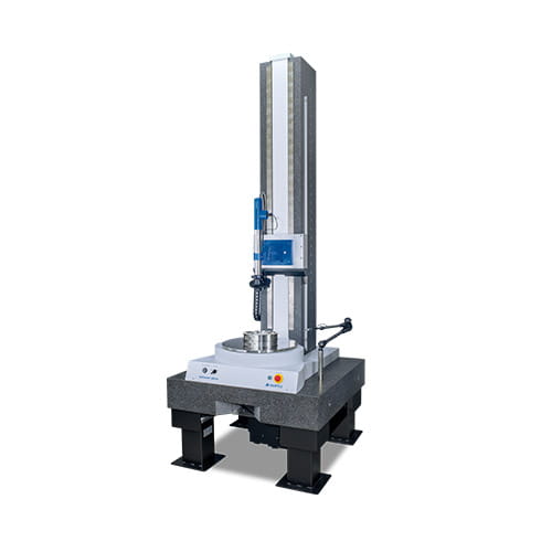
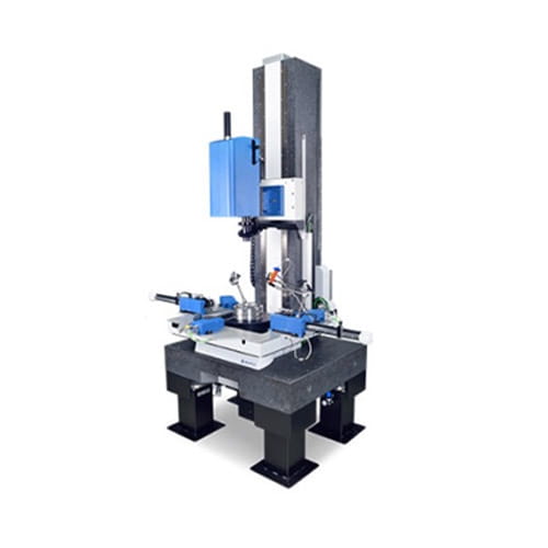
OptiCentric® 300 UP
Stability for large and heavy samples
The granite base of the OptiCentric® 300 UP provides outstanding rigidity and long-term stability for the testing and alignment of lenses with a diameter of up to 400 mm.
- Precision < 0.1 µm
- Maximum axial sample weight of 450 kg
- Motorized air bearing linear stage with a travel path of 1000 mm
The OptiCentric® 300 UP can be configured in a modular way depending on individual requirements
You will find further information on the expansion stages further down on this page.
Upgrades for further measurement tasks:
- Testing of lens systems with more than 20 surfaces
OptiCentric® 300 UP Dual
- Centration testing in combination with center thickness and air gap measurement
OptiCentric® 3D 300 UP
- Centration testing of lens systems with more than 20 surfaces in combination with center thickness and air gap measurement
OptiCentric® 3D 300 UP Dual
- Testing of VIS and IR lens systems
OptiCentric® 300 UP IR
- Centration testing of VIS and IR lens systems in combination with center thickness and air gap measurement
OptiCentric® 3D 300 UP IR
- Centration testing of VIS and IR lens systems in combination with center thickness and air gap measurement
OptiCentric® 300 UP Dual IR
- Centration testing of VIS and IR lens systems with more than 20 surfaces in combination with center thickness and air gap measurement
OptiCentric® 3D 300 UP Dual IR
- Centration testing in combination with the testing of effective focal length and back focal length, flange focal length, radius and MTF
OptiCentric® 300 UP with OptiSpheric®
- Centration test for cylinder lenses
OptiCentric® 300 UP with CylinderCheck®
OptiCentric® 600 UP
Precise centering of heavy weights
Lens assemblies with a diameter of up to 600 mm are centered and aligned safely using the OptiCentric® 600 UP.
- Precision < 0.1 µm
- Maximum axial sample weight of 900 kg
- Motorized air bearing stage with a travel path of 1500 mm
The OptiCentric® 600 UP can be configured in a modular way depending on individual requirements.
You will find further information on the expansion stages further down on this page.
Upgrades for further measurement tasks:
- Testing of lens systems with more than 20 surfaces
OptiCentric® 600 UP Dual
- Centration testing in combination with center thickness and air gap measurement
OptiCentric® 3D 600 UP
- Centration testing of lens systems with more than 20 surfaces in combination with center thickness and air gap measurement
OptiCentric® 3D 600 UP Dual
- Testing of VIS and IR lens systems
OptiCentric® 600 UP IR
- Centration testing of VIS and IR lens systems in combination with center thickness and air gap measurement
OptiCentric® 3D 600 UP IR
- Centration testing of VIS and IR lens systems in combination with center thickness and air gap measurement
OptiCentric® 600 UP Dual IR
- Centration testing of VIS and IR lens systems with more than 20 surfaces in combination with center thickness and air gap measurement
OptiCentric® 3D 600 UP Dual IR
- Centration testing in combination with the testing of effective focal length and back focal length, flange focal length, radius and MTF
OptiCentric® 600 UP with OptiSpheric®
- Centration testing of aspheres
OptiCentric® 600 UP with AspheroCheck®
OptiCentric® 800 UP
Largest samples – maximum precision
The OptiCentric® 800 UP is recommended for the testing and alignment of the largest sized lens assemblies – up to a diameter of 800 mm.
- Precision < 0.1 µm
- Maximum axial sample weight of 1200 kg
- Motorized air bearing stage with a travel path of 1500 mm
The OptiCentric® 800 UP can be configured in a modular way depending on individual requirements.
You will find further information on the expansion stages further down on this page.
Upgrades for further measurement tasks:
- Testing of lens systems with more than 20 surfaces
OptiCentric® 800 UP Dual
- Centration testing in combination with center thickness and air gap measurement
OptiCentric® 3D 800 UP
- Centration testing of lens systems more than 20 surfaces in combination with center thickness and air gap measurement
OptiCentric® 3D 800 UP Dual
- Testing of VIS and IR lens systems
OptiCentric® 800 UP IR
- Centration testing of VIS and IR lens systems in combination with center thickness and air gap measurement
OptiCentric® 3D 800 UP IR
- Centration testing of VIS and IR lens systems in combination with center thickness and air gap measurement
OptiCentric® 800 UP Dual IR
- Centration testing of VIS and IR lens systems with more than 20 surfaces in combination with center thickness and air gap measurement
OptiCentric® 3D 800 UP Dual IR
- Centration testing in combination with the testing of effective focal length and back focal length, flange focal length, radius and MTF
OptiCentric® 800 UP with OptiSpheric®
- Centration testing of aspheres
OptiCentric® 800 UP with AspheroCheck®
Expansion stages
OptiCentric® 3D
Determine center thickness and air gaps
The expansion stage 3D permits the complete opto-mechanical characterization of mounted optical systems using the OptiCentric®.
- Combined measuring instrument for centration testing and center thickness/air gap measurement
- Precision of centration measurement < 0.1 µm
- Maximum measuring length of 800 mm
OptiCentric® Dual
Speed up lens assembly
Every OptiCentric® can be equipped with a second measurement head for testing more complex lens assemblies with increased flexibility.
- Compact standalone unit for centration testing of complex optical systems
- Simultaneous measurement with two optical heads shortens process time
- Rigid system allows for highly precise lens alignment
OptiCentric® IR
Centration testing of IR lens assemblies
The OptiCentric® is enhanced by an IR-measurement head for the setup and testing of assembled infrared lens assemblies.
- Automatic changeover between MWIR, LWIR and VIS
- Precision: 0.25 µm for IR
- High operating comfort: visual and IR systems are operated in the same way
LensAlign
Automated alignment and cementing
OptiCentric® with LensAlign makes a significant increase in alignment precision possible and manufacturing throughput.
- Alignment precision better 2 µm
- Automatic alignment of the center of curvature of the upper surface to a defined axis using the SmartAlign technology
- Automated process: software-controlled measurement, alignment and UV-curing
Complete systems
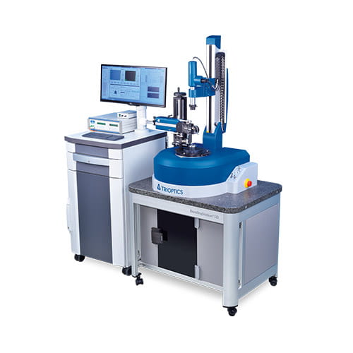
OptiCentric® Bonding 2D
Fully automatic bonding of lenses in cells in two degrees of freedom
Automated centration testing, alignment and bonding of lenses in cells is made possible in two degrees of freedom by the OptiCentric® Bonding 2D.
- Alignment accuracy < 2 µm
- Alignment and bonding based on the SmartAlign software module
- Equipped with three actuators for an automated alignment process
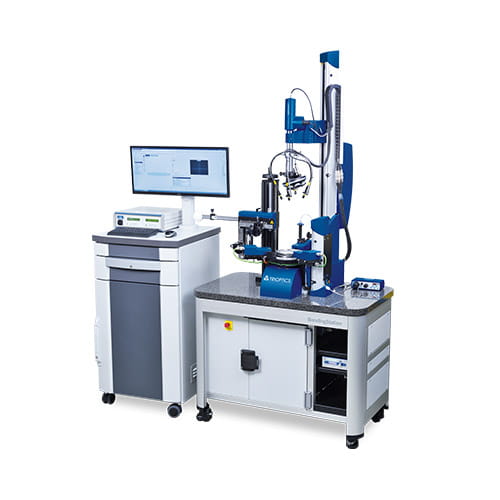
OptiCentric® Bonding 5D
Highly accurate bonding and testing of precision optics with five degrees of freedom
Precision optics are tested very accurately using the OptiCentric® Bonding 5D and bonded in five degrees of freedom in cells.
- Positioning accuracy X/Y/Z < 1 µm; θX, θY < 2 arcsec
- Automated process flow
- Operator independent results
OptiCentric® UP Bonding
Precise alignment and bonding of large and heavy lenses in a cell
The setup of precision optics with a diameter of up to 800 mm and a wight of 1200 kg takes place using OptiCentric® UP Bonding in two degrees of freedom.
- Alignment precision better 2 µm
- Automatic and precise height adjustment of the bonding frame in order to make the gradual setup of objectives up to a height of 1.5 m possible
- Extremely efficient process since the time-consuming replacement of alignment and bonding tools is no longer necessary
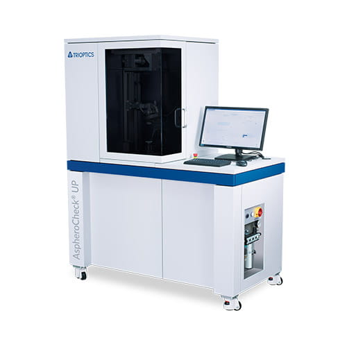
AspheroCheck® UP
Fully automated centration testing of aspheres
AspheroCheck® UP permits the automatic testing of centering error and tilt of aspheric lenses
- High measurement accuracy of 0.1 µm for centration and 0.05 arcmin for tilt
- Automatic positioning of the sample and non-contact sensor
- Completely automated measurement for the rapid collection of results in less than 1 minute


Software
- Immediate checking of the measurement process through real display of the measured values during measurement of the centering errors
- Coordinated control and evaluation of all axes for efficient measurement
- Data capture and evaluation of all integrated sensors provides immediate results
- Auto-focus makes reproducible measured values possible
- Optional software extensions for the measurement of lens assemblies, aspheres and cylinder lenses
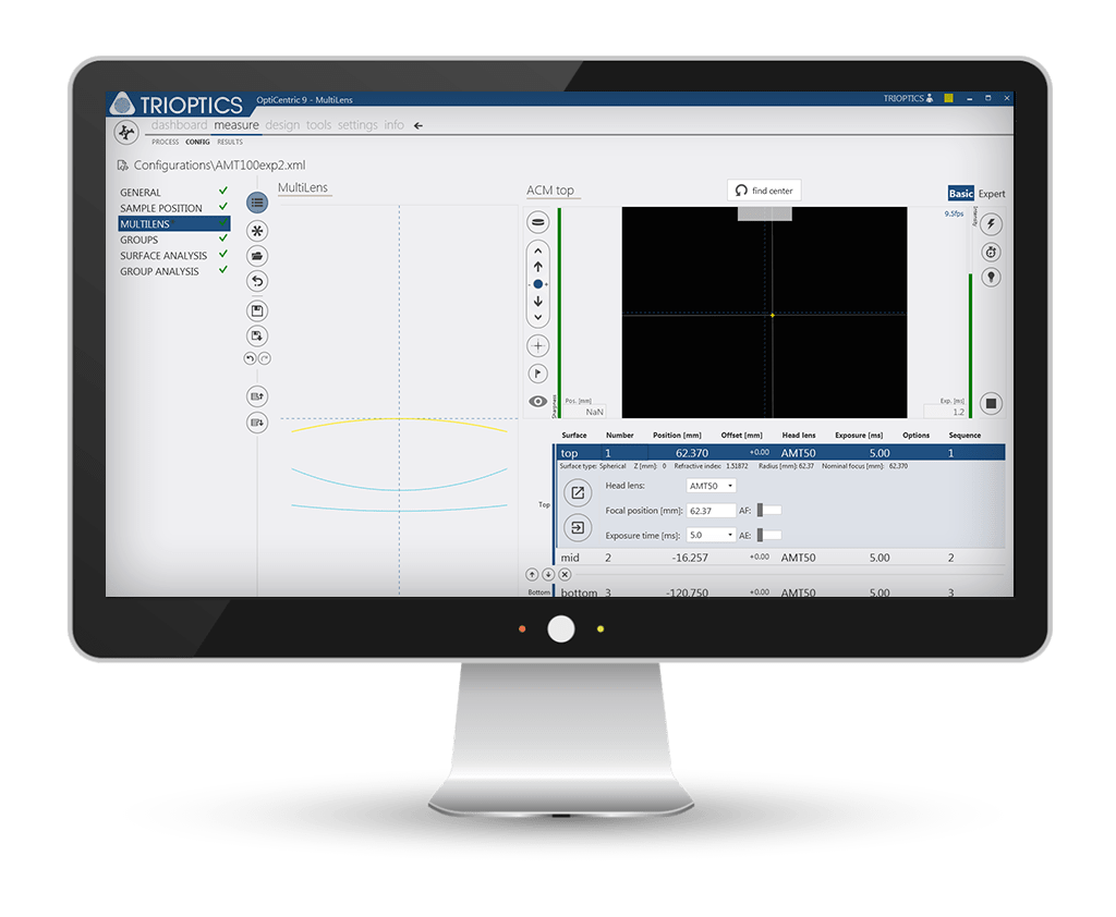
- Patented MultiLens software module for the measurement of complex lens assemblies
- Centering error calculation and alignment independent of the measurement environment through a freely definable mechanical or optical reference axis (SmartAlign)
- Data import and export allows fast and complex documentation
- Immediate evaluation of sample quality through scrap analysis according to individual testing criteria.
- Optimized production workflows thanks to application-specific user interfaces for cementing and bonding, further customer-specific adaptation on request
MultiLens: Measurement and alignment of objectives towards a freely selectable reference axis
MultiLens is the software module for measuring and aligning lens assemblies. The centering errors of each individual surface of a lens assembly and the centering of the system are determined non-destructively. With this information, the centration of a single lens or a sub-group can be calculated with respect to a freely selectable reference axis.
SmartAlign: Correct centering errors automatically
With the SmartAlign Module, the position of the measured centering error is analyzed in reference to a user-defined optical or mechanical axis. This unique tool is used especially successfully in the automated LensAlign alignment modules and bonding systems.
Upgrades
- Turning and holding devices for samples
- LensAlign for cementing lens to lens
- LensAlign for cementing lens to arbor
- Measurement heads
- Additional measurement functions
- Workstation
- Software modules
- Other accessoires
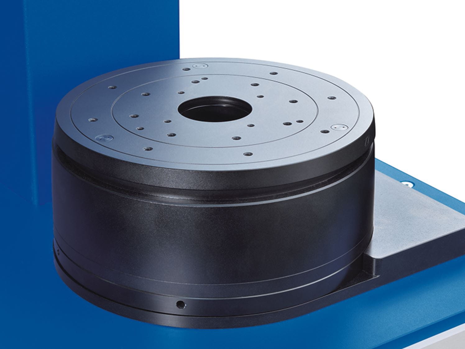
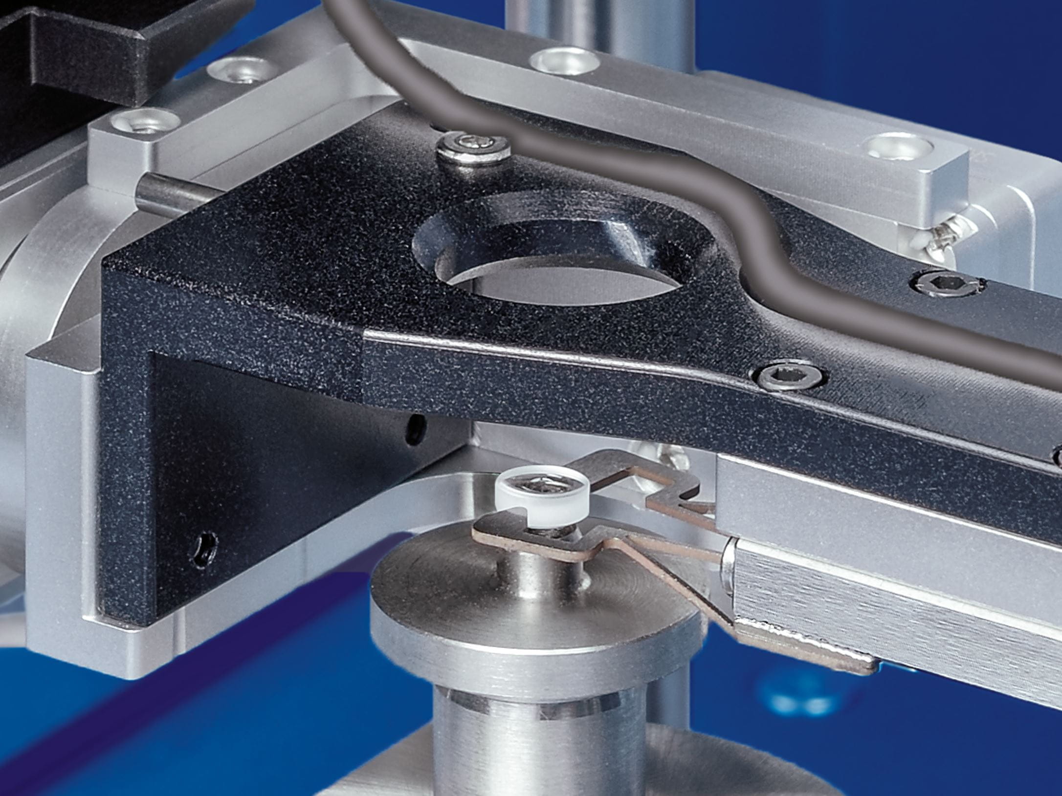
A precise pivot bearing represents the measuring reference of high-precision centration testing. All OptiCentric® systems are equipped with an air bearing, optionally a mechanical lens rotation device can be used for measurement of single lenses and doublets.
An OptiCentric® system equipped with an air bearing is required for the following applications:
- Testing lens assemblies
- Setting up lens assemblies
- Alignment of doublets with the optical axis of the lower lens as reference
- Alignment and centering of lenses on a centering arbor with the arbor axis as reference
- Testing of aspheres using the AspheroCheck® module
- Single lens measurement on sensitive lenses e.g. calcium fluoride lenses
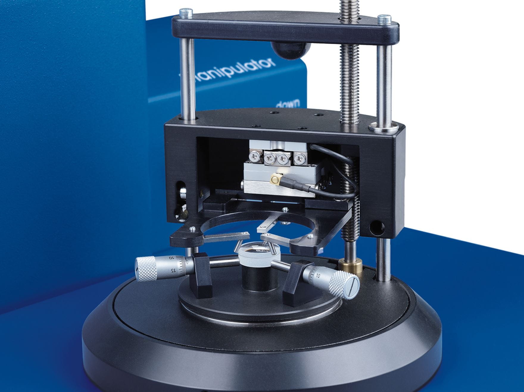
Manual tip-tilt table (TRT)
OptiCentric® systems use tip-tilt tables to align samples. The decoupled movements of the tip-tilt tables allow for precise positioning of the sample or sample holder. Tip-tilt tables are available in different diameters for a variety of applications and measurement systems.
Motorized tilt and translation table (TRT)
For easier sample handling during measurement or setup of an optical system, the OptiCentric® 3D 100 in particular can be equipped with a tilt and translation table (TRT). Instead of the traditional manually alignement, the motorized TRT tilts and shifts the sample such that the optical axis of the lens is aligned to match the reference axis of the system. This is performed fully automated and embedded in the process flow, thus permitting a shortened test cycle.
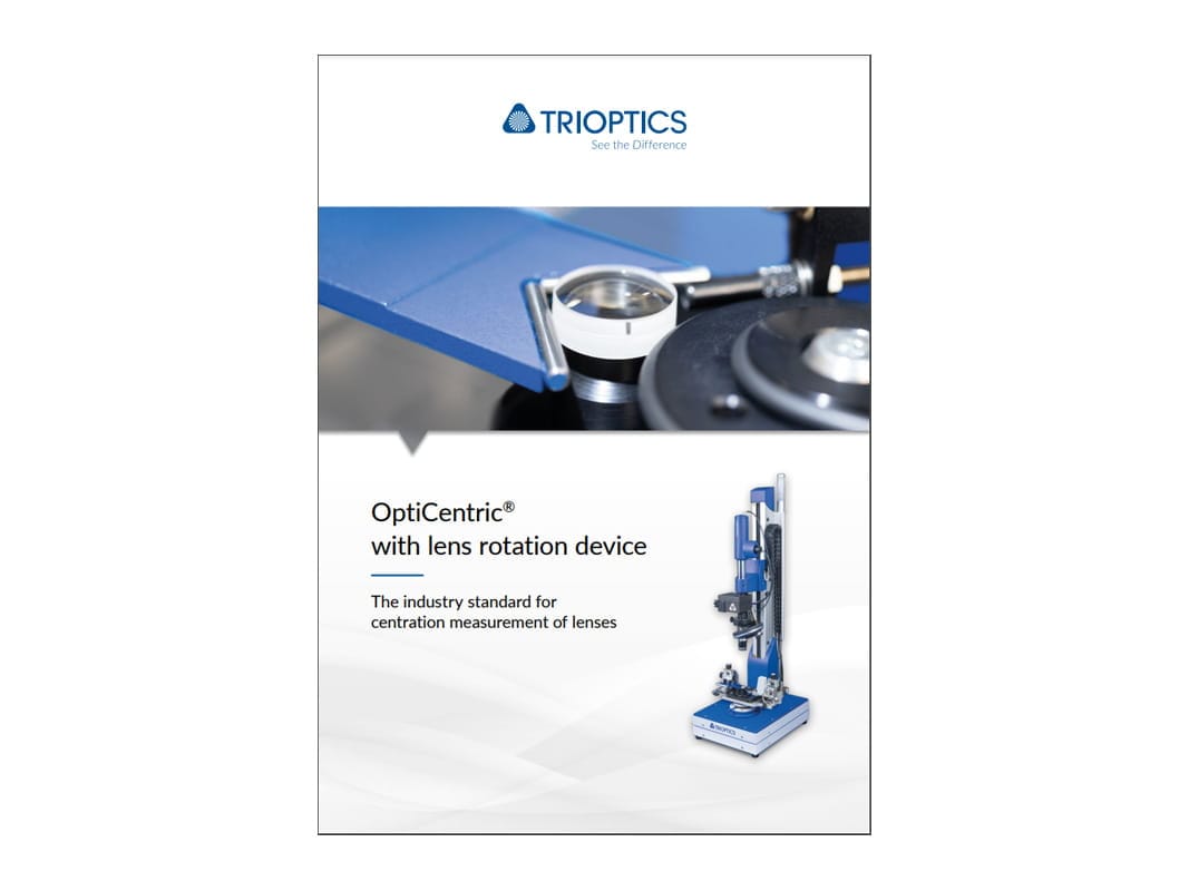
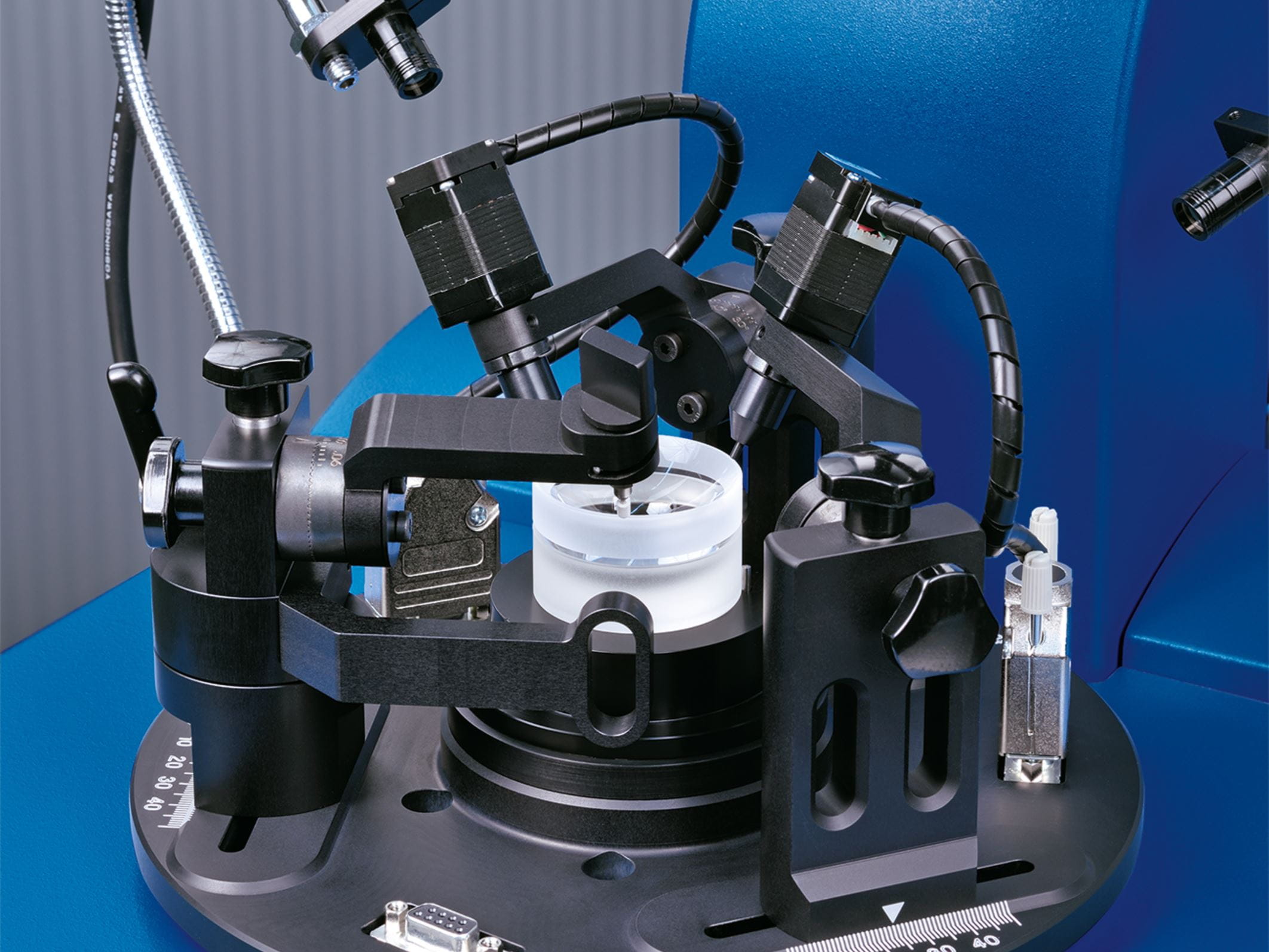
Lens rotation device
The motorized rotation device is a rotation device to
- measure single lenses with a diameter up to 200 mm using the outer edge and the center of curvature of the lower lens as a reference
- cementing doublets. In this case, the reference axis comprises the center of the circumference and the center of curvature of the lower lens.
No air bearing is required for the motorized rotation device. Equipped with a so-called “bridge”, the lens rotation device can be operated on OptiCentric® 100, 101 and 300 units which are equipped with an air bearing.
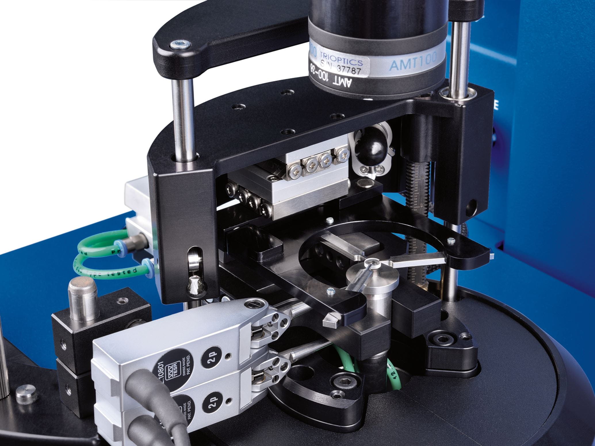
LensAlign 2D Air
The module LensAlign 2D Air enhances OptiCentric® systems by adding a software-controlled air manipulator and offers a cost-efficient solution for an entry-level active automated lens alignment. As the process enabled by LensAlign 2D Air does not require operator interaction, a persistent sample quality and an improved process safety can be guaranteed.
LensAlign 2D Standard
An OptiCentric® system that is equipped with the LensAlign 2D Standard for cemented elements aligns and cements lenses with a geometry of D/(2R) ≤ 0.7. The unit can be easily adapted to different lens sizes and is recommended when lenses have to be cemented together to the optical axis within short notice.
LensAlign 2D Advanced
The LensAlign 2D Advanced module was developed to meet the increased requirements of our customers. The LensAlign 2D Advanced aligns all lens geometries, including:
- Lenses with D/(2R) > 0.7
- Hemispherical lenses Doublets where the edge of the upper lens is not accessible
- Lenses with tight tolerances for the cement wedge
LensAlign 2D Advanced for Mikrolinsen
Equipped with three actuators, the LensAlign 2D Advanced module permits the alignment of micro-lenses. There are no limitations to lens geometry here.
LensAlign 2D Standard
The LensAlign 2D Standard for the alignment and centering of lenses to an arbor is suitable for lenses with a geometry of D/(2R) ≲ 0.7. The unit can be easily adapted to different lens sizes and is recommended when lenses have to be cemented to the arbor axis quickly. Following alignment and centering on the arbor, the process can be continued for the alignment of further lenses.
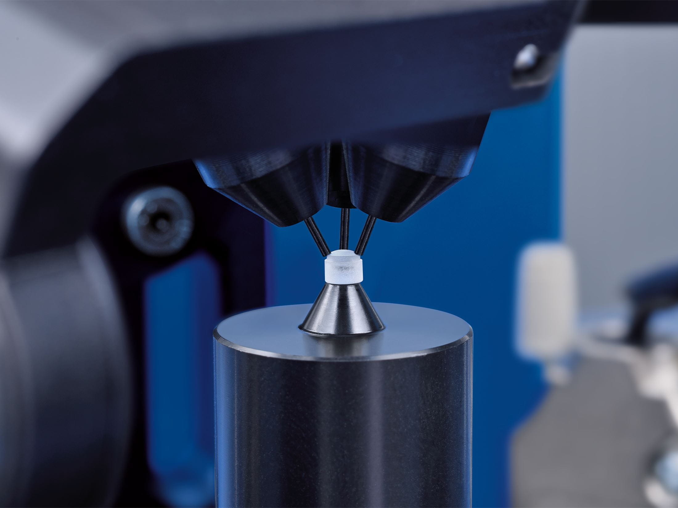
LensAlign 4D
LensAlign 4D represents a module for the OptiCentric® 101 that enables the cementing of a small lens to a mechanical reference axis, such as an arbor or cell. In this setup, alignment is performed without the constraint of a mechanical lens seat, which can restrict lens alignment. For precise positioning, the lens is positioned on a thicker layer of adhesive and initially held by a micro-gripper, which shift and tilts the lens in four degrees of freedom until the optical axis aligns with the mechanical axis. This achieves a high precision alignment. Following alignment and centering on the arbor, the process can be continued for the alignment of further lenses.
OptiCentric® systems determine the centering errors of optics, with a high degree of accuracy and in real time. The measurement head required for this comprises an electronic autocollimator with camera and LED lights with reticle.
TRIOPTICS supplies two measurement heads for the OptiCentric® systems, from which the suitable one must be selected depending on the application:
- VIS measurement head (standard)
- IR measurement head for testing MWIR and LWIR lens assemblies
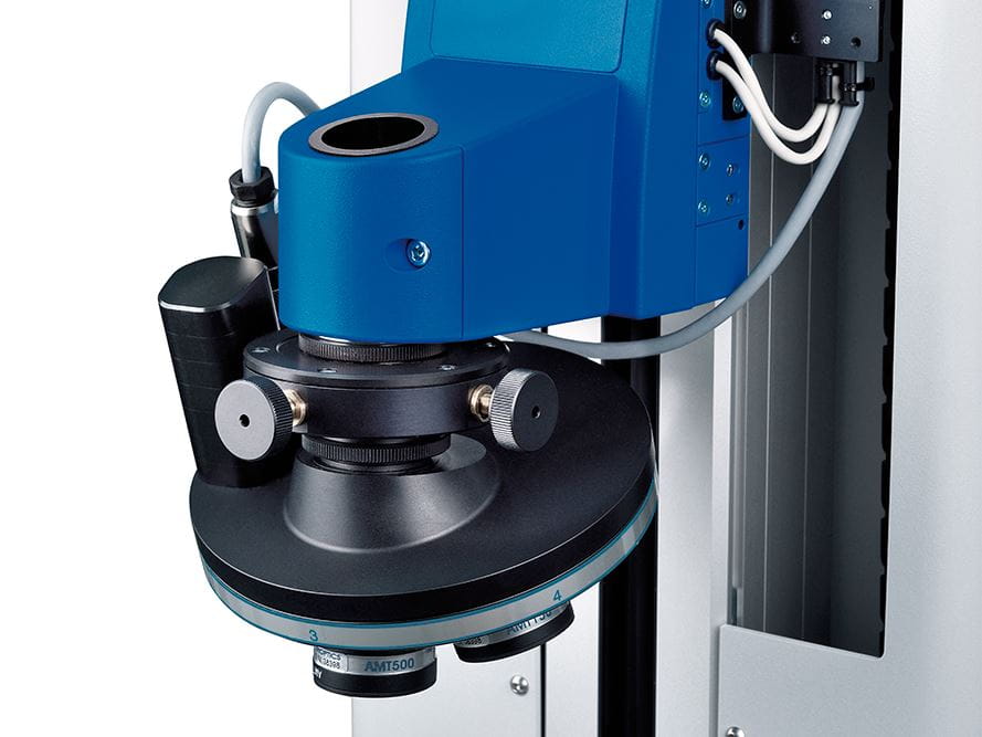
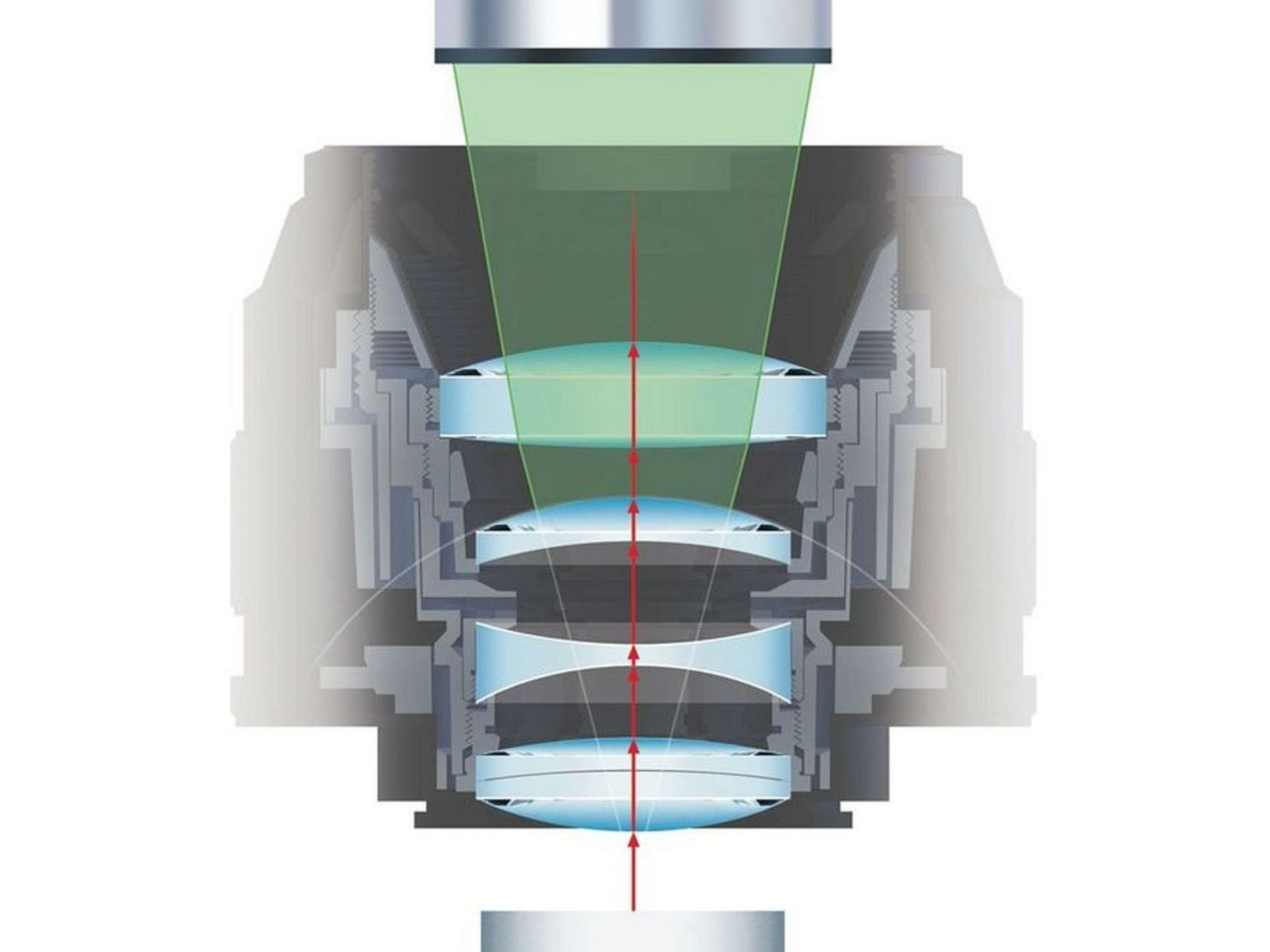
Changer for head lenses
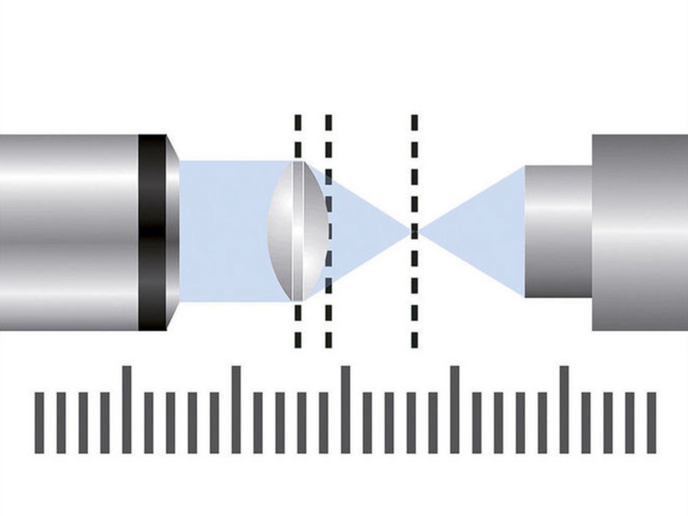
In order to be able to focus on the center of curvature (reflection measurement) or on the focus position (transmission measurement) of different lenses, the measurement heads are equipped with head lenses, resulting in unbeatable benefits:
- Optimized magnification for each individual lens surface
- Practically unlimited measurement range
- No long, time-consuming movements of the measurement head
In order to be able to replace the head lenses quickly and without complications, it is possible to equip the systems with manual or motorized turrets.
OptiCentric® 101/300 IR is TRIOPTICS’ solution for centration testing of infrared optics. The system is equipped with a flexible-changeover VIS-MWIR and/or VIS-LWIR measurement head and can test all types of infrared optics.
OptiSpheric® upgrade: supplementary optical measuring parameters
The OptiSpheric® upgrade can be used for the comprehensive testing of optical parameters in one unit. With this, the measuring range is extended by the following parameters:
- Effective Focal Length (EFL)
- Back Focal Length (BFL)
- Flange Focal Length (FFL)
- Radius of curvature
- Modulation Transfer Function (MTF) on-axis
For the complete opto-mechanical characterization of optical systems which are already mounted, the OptiSurf® low-coherence interferometer is integrated into the OptiCentric® system, which is then called the OptiCentric® 3D 100. This combination of both measurement systems results in a significant increase in measurement accuracy. The center thicknesses and lens distances can only be determined with maximum accuracy as a result of the highly accurate centration testing and subsequent adjustment of the sample. The center thickness and the air gaps within a lens assembly of up to 800 mm in optical thickness are measured in a single scan. Operation is also extremely simple thanks to complete integration in the OptiCentric® software.
CylinderCheck®
CylinderCheck® is used for contactless quality control of cylindrical lenses and lens systems containing cylindrical elements. For single lenses using both the CylinderCheck® hardware and software module allows the measurement of:
- the centration and parallelism of the cylinder axis and the mechanical datum,
- the clocking error of the cylinder axis to a mechanical datum or with respect to the cylinder axis on the second side of the element and
- the wedge angle between the cylinder axis and the element’s second cylindrical or flat surface.
The measurement of lens systems containing cylindrical lenses can be performed on an OptiCentric® 101 with rotary air bearing and CylinderCheck® software.
AspheroCheck®
AspheroCheck® is a hardware and software module that measures the slope and position of an aspherical axis relative to a given reference axis. The upgrade is characterized by:
- Measurement in reference to the optical axis of the asphere or to a reference axis
- Specified reference axis according to DIN ISO 10110-6
- Measurement of lenses with one or two aspherical surfaces
- Sample diameters from 2 mm
- Accuracy up to 5 arcsec (depending on the sample geometry)
- Contact-free measurement
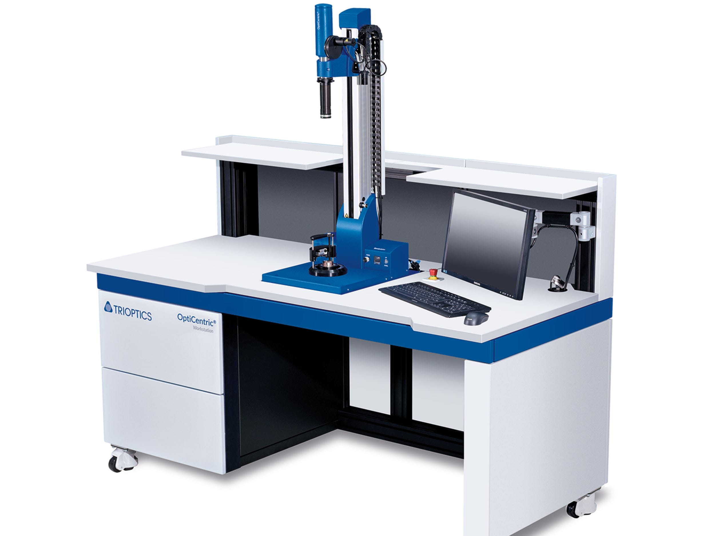
Workstation
With the workstation, the OptiCentric® measurement system is turned into a complete workplace. Alongside integration of the controller and the PC equipment, the workstation provides enough working space for preparing and post-processing the samples. Space and storage areas allow good organization of the workstation.
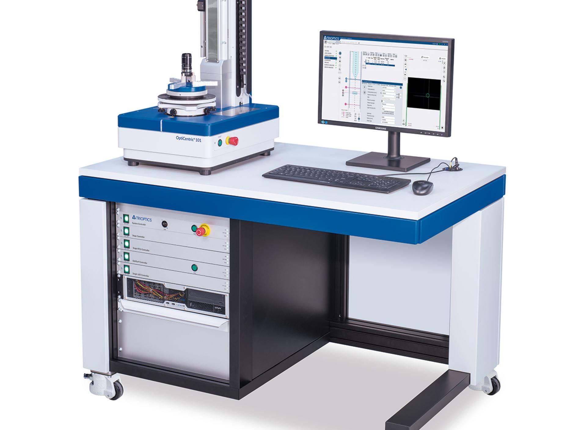
Worktable S
The worktable is the perfect supplement to table-top devices such as the OptiCentric® 101. The system is thus given a sturdy table where the controller is integrated. The monitor and additional PC equipment are attached and can be operated close to the system.
MultiLens is the software module for measuring and aligning lens assemblies. The centering errors of each individual surface of a lens assembly and the centering of the system are determined non-destructively. With this information, the centration of a single lens or a sub-group can be calculated with respect to a freely selectable reference axis
SmartAlign: Correct centering errors automatically
With the SmartAlign Module, the position of the measured centering error is analyzed in reference to a user-defined optical or mechanical axis. This unique tool is used especially successfully in the automated LensAlign alignment modules and bonding systems.
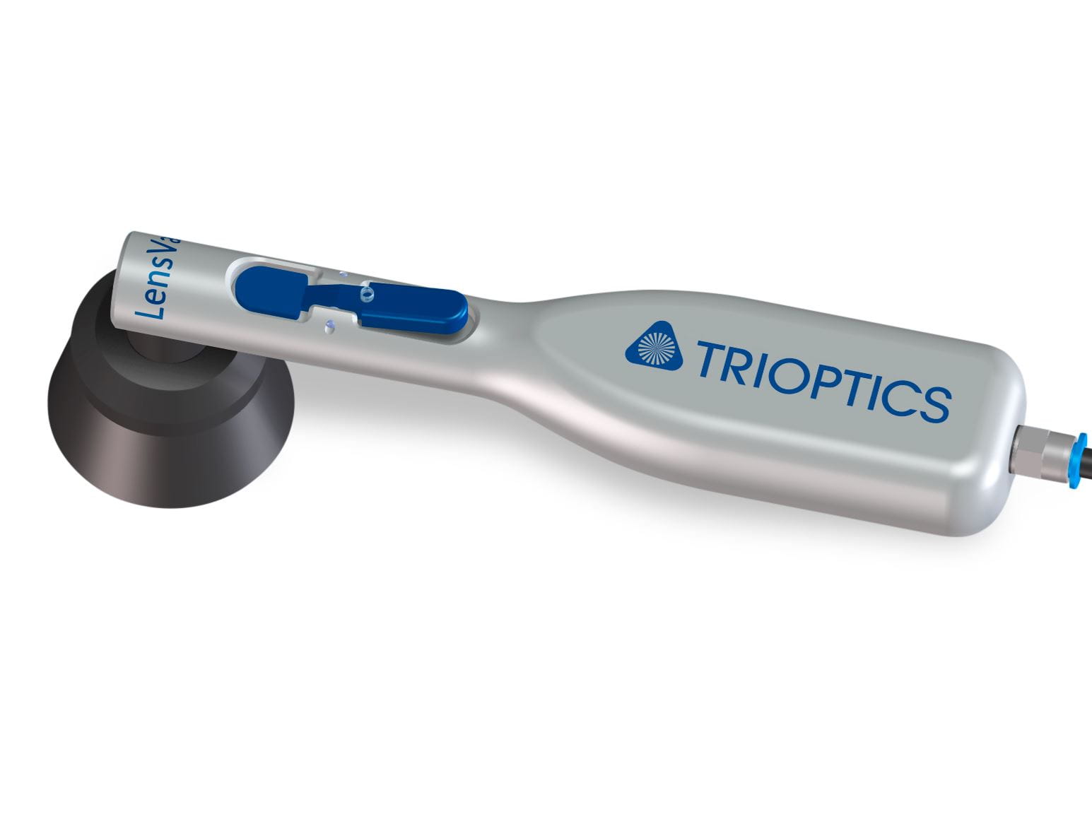
LensVac
The vacuum tweezers LensVac support the safe and clean handling of optical components for the loading and unloading of lenses into trays as well as the insertion of the optical elements into their lens barrel.
- Exchangeable vacuum cups for small & medium sized lenses (up to 100 mm)
- L-shape tweezers for handling under tight space requirements
- Activation via thumb switch
- Compatible with different approaches for vacuum generation (available on request)
Other accessoires
- Measuring probe
- For determining the position of optics before adjustment
- Expansion of measurement range to effective focal lengths of up to ±2,000 mm
- Alignment set, calibration wedges
- Samples, traceable by PTB
- Lens holder and ring chucks
- Foot-pedal control for the compressed air
- Tool-stage with kinematic seat for holding the alignment tools
- UV light source, manual bonding unit with foot pedal, automated bonding unit, needles and tubes for the bonding unit
Are you interested in a product and would like to receive a quote?
Whether you need advice or already have specific requirements, we will be happy to help you!
Use our contact form and get quick feedback from our experts.Our Newsletter – Your advantage in knowledge
Be one of the first to experience our product novelties and innovative application possibilities.