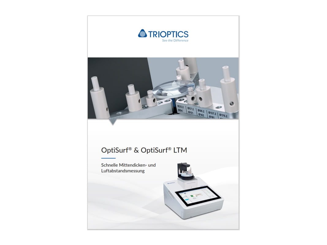
OptiSurf®
High-precision measurement of center thicknesses and air gaps
Highly precise
Gentle on material
Easy to use
Products
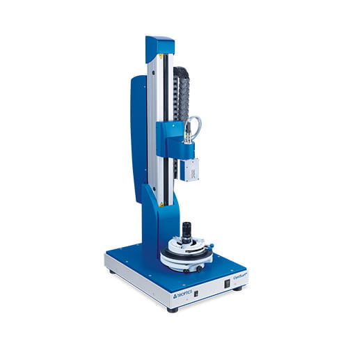
OptiSurf®
The standard for center thickness measurement
OptiSurf® is the standard for measuring center thickness and air gaps.
- Measurement accuracy of up to 1 µm
- Measurement head with automatic focusing
- Integrated visual laser beam for preliminary alignment of the sample
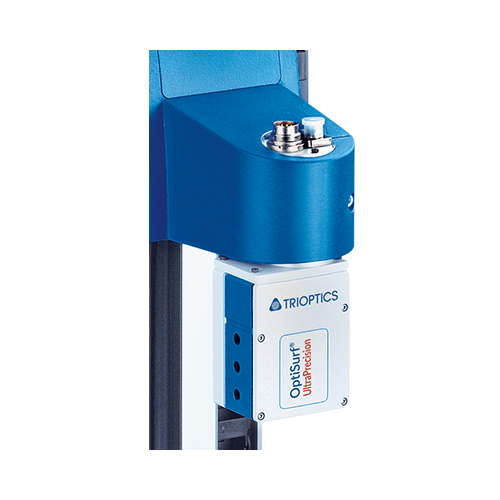
OptiSurf® UP
For the highest demands
The OptiSurf® UP meets the highest requirements with its ultra-precise center thickness and air gap measurements.
- Measurement accuracy of up to 0.15 µm
- Measurement head with automatic focusing
- With temperature and air pressure sensors
- Integrated visual laser beam for preliminary alignment of the sample
OptiSurf® IR OEM
Measurement of all IR materials
The unique measurement head OptiSurf® IR OEM allows the measurement of center thicknesses and air distances of IR lenses.
- Single sensor with delay line for easy customized integration
- Measurement accuracy of up to 5 µm
- Measurement head with automatic focusing
OptiSurf® OEM
Individual fitted
The OptiSurf® OEM can be integrated into external systems for customer-specific linking of center thickness and air gap measurements with further measurement parameters.
- Single sensor with delay line for integration in non-TRIOPTICS measurement systems
- Measurement head with automatic focusing
Software
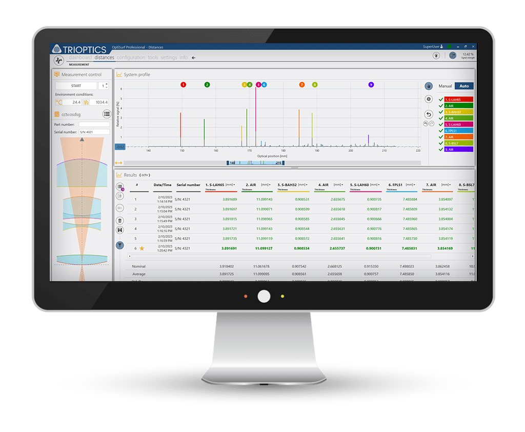
OptiSurf®
Fast, comprehensive and user-friendly
OptiSurf® software allows the quick and comprehensive measurement and analysis of center thicknesses and air gaps in optical systems. Both the signal curve as well as color markings in the lens system scheme permit conclusions to be drawn quickly with regard to the plausibility and completeness of the measurement. Performing multiple measurements with a statistical evaluation allows a highly reliable evaluation to be carried out.
- Supports the intuitive handling, alignment and measurement process
- Automated surface identification for quick and precise measurements
- Automated evaluation and identification of deviations by means of a pass/fail analysis
- Product-specific quality control through the statistical analysis of measurement results
- Easy input of sample data directly via Zemax, OptiCentric® or via a design editor
Downloads

Upgrades
For fast and validated testing, TRIOPTICS offers the following accessories

Are you interested in a product and would like to receive a quote?
Whether you need advice or already have specific requirements, we will be happy to help you!
Use our contact form and get quick feedback from our experts.Our Newsletter – Your advantage in knowledge
Be one of the first to experience our product novelties and innovative application possibilities.