

Measurements with collimator and industrial telescope
While collimators project a structure engraved on a reticle to a certain finite or infinite distance, industrial telescopes are used for the visual inspection of objects at a fixed distance. TRIOPTICS offers both optical instruments within the OptiTest® product group. Numerous options such as different reticles, wavelengths and focusing are available. The combination of a collimator with an industrial telescope is used for the application of angle measurements, image quality testing or measurement of optical parameters.
Angle measurement
Angle measurement
A telescope mounted in the front of a collimator enables the simultaneous observation of both collimator and telescope reticle. When a collimator is perfectly aligned to a telescope the reticles are superimposed and no displacement occurs.
The presence of an angle α between the collimator and telescope axes is shown by a linear displacement d between the two reticles. The displacement d gives the size of the angular disalignment (in radians) of the two instruments:
α = d/f

where:
d=linear displacement measured in the reticle plane (focal plane)
f=effective focal length (EFL) of the observing instrument (i.e. telescope)
To ease the angular alignment of equipment with flat surfaces a special type of instruments can be used: the square body collimators and telescopes. The reticles of these instruments are accurately aligned to the outer square body surfaces.
Measurement of the transmission angle through prisms

Absolute measurement: The telescope is attached to a precision rotary table with read out:
First reading: collimator and telescope aligned (without sample)
Second reading: sample positioned, telescope rotated until the reticles are super imposed. Reading on rotary table.
Relative measurement: a master prism is used, collimator and telescope rotated until reticles are super imposed and fixed in this position. The sample is placed instead of master prism. Reading on telescope.
Alignment of prism systems

The collimator and the telescope are strictly aligned. When the binoculars or the prism system only are placed between the collimator and telescope tilt and rotation of prisms can be measured.
Measurement of optical parameters
Measurement of focal length

A typical application is the measurement of the effective focal length EFL. A highly corrected collimator set to infinity (emerging beam is parallel) has a reticle with a pair of spaced lines located in its focal plane. The image of the reticle is projected over the lens under test and focused in its focal plane. By means of a microscope (or a telescope with a supplementary achromat) the size of spaced lines is determined and the EFL calculated: f = fcol x S’/S
Measurement of centration errors

A collimator set to infinity contains a reticle with a dark or bright cross. The lens under test is placed in a precision rotary holder. The image of a reticle projected over the lens under test is observed by means of a telescope with additional achromat having a graduated reticle.
While rotating the holder with the lens, the circle described by the reticle image is measured.
Measurement of the focusing distances

Many telescopes and sighting devices are designed to be focused at different distances over a given range. To measure the distance setting of sighting devices a focusing collimator with a accurately graduated draw out tube is focused at the distance to be checked. Through the eyepiece of the sighting device the collimator reticle is observed. If the image of the collimator reticle appears sharp within the required tolerance, the sighting device is correctly adjusted. Deviations are measured and read off on the graduated draw out tube of the collimator.
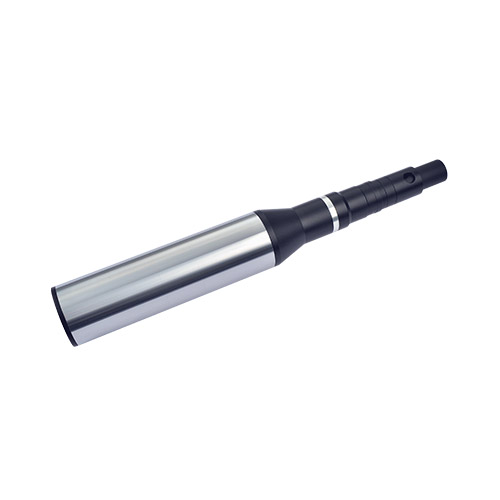
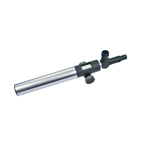
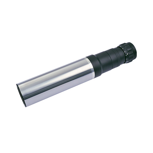
Our products
Our telescopes and collimators are combined in the OptiTest® product group. They are available in the following variants:

Knowledge Base
Collimator
The collimator is an optical instrument consisting of a well corrected objective lens with
an illuminated reticle at its focal plane or close to it. The reticle position determines whether the outgoing beam is collimated, or a real or virtual image is formed.

Illustration 1
The reticle is placed at the lens focal plane. The emerging beam is collimated, meaning that all rays originated from the same point on the reticle plane are parallel to each other. The image of the reticle is said to be projected to infinity because parallel rays will not cross at a finite distance.
Illustration 2
The reticle is placed beyond the focal plane
of the objective lens. The emerging beam is convergent, meaning that rays originated from the same point on the reticle plane meet again at a single point on the right side of the lens, leading to the formation of a real image at a finite distance.
Illustration 3
The reticle is placed between the lens and its focal plane. The emerging beam is divergent and there exists an apparent crossing point on the left side of the lens which is equivalent to an object placed at that point from where the divergent rays are originated. This image is said to be virtual.
Fig. 2 shows a schematic representation of the cross section of a collimator. Reticle and objective lens are the most important components and are mounted in a tube. On the left side there is a light source, followed by a diffuser and a set of condenser lenses that fulfill the purpose of obtaining a more homogeneous intensity distribution across the reticle pattern.

More knowledge for experts
This article inspired you? Are you looking for further knowledge transfer?
Then you might also be interested in the following topics…
Industrial telescope
The telescope reverses the collimation process described before. An object placed at infinity, corresponding to a collimated light beam, will be imaged on the focal plane of the telescope objective (or close to it for objects placed close to infinity). Inspection of the image can be carried out either by an electronic 2D sensor placed directly at the image plane of the telescope, or visually via an eyepiece. In the case of visual inspection, usually a graduated reticle is placed in the image plane of the lens, providing a numerical reading for the position of the image on the focal plane.

Fig. 3 Schematic cross section of a telescope. Visual inspection by an eyepiece.
